


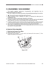
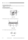
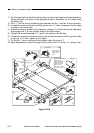
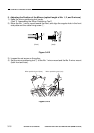
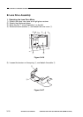

1) Put the steel ball into the hole of the pulley, and wind the cable four times toward the
flange and then nine times in the opposite direction; thereafter, fix it in place using
the pulley clip.
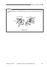
2) As in w, set the mirror positioning tool between the No. 1 and No. 2 mirror mounts.
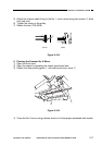
3) Loosen the screw on the mirror pulley mount as in e; then, temporarily fix the cable
in position on the left stay.
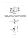
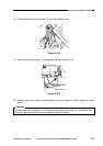
4) Route the cable as shown in the illustration; engage t on the hook on the side plate,
and engage the i on the tension plate on the lens mount.
5) Tighten the screw loosened in e, and fix the cable to the left stay.
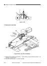
6) Loosen the screws on the drive pulley once so that the tension of the scanner cable
is even as in !0; then, tighten it once again.
7) Fix the No. 1 mirror mount and the scanner cable fixing as in !1.
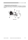
8) Make adjustments so that the length of the cable is 34 ±1 mm as in o using a ruler.
Figure 3-410
COPYRIGHT
©
1997 CANON INC. CANON NP6218 REV. 0 MAY 1997 PRINTED IN JAPAN (IMPRIME AU JAPON)
CHAPTER 3 EXPOSURE SYSTEM
3-14
Screw
Losen the screw,
and shift.
Re-tighten
the screw.
Set the mirror
positioning tool
Set screws
Loosen the set
screw to free the
totation of the
pulley.
Put the steel ball into
the hole in the
pulley, and wind the
cable nine times
toward the inside
and four times
toward the outside;
then, fit the pulley clip.
Pulley clip
Steel ball
34±1mm
o
y
u
r
!1
t
q
!0
w
e
i