


COPYRIGHT
©
1997 CANON INC. CANON NP6218 REV. 0 MAY 1997 PRINTED IN JAPAN (IMPRIME AU JAPON)
7-2
CHAPTER 7 EXTERNALS/AUXILIARY MECHANISMS
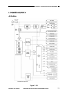
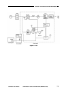
B. Power Supply Circuit Assembly
The copier’s power supply assembly is a composite power supply circuit which uses
a single main transformer (T101) as the source of DC power, high-voltage power, and
power for the fluorescent lamp.
AC power is supplied to the DC power supply assembly when the power switch
(SW829) and the door switch are turned on.
When the power switch on the control panel is pressed, signals are sent to the
composite power supply assembly to generate internal power supply +5 Vin.
In response, the microprocessor (Q512) turns on to turn on relays RL101 and RL501
to supply power.
The DC power supply generates +34 V, +24 V, and +5 V.
When the power switch is pressed for a second time, the microprocessor turns off
RL501 and the main transformer; thereafter, it turns off Q503 to turn off RL101, thereby
cutting off +5 Vin.
The condition deprives the DC controller circuit of DC power; to compensate for the
absence of power, a lithium battery (BAT301) is provided to back up the data in the RAM
(Q307) in the DC controller circuit.
Caution:
Voltage is supplied up to the AC power supply even when the power is off.
Caution:
Replace the lithium battery only with the one listed in the Parts Catalog. Use of a
different battery may present a risk of fire or explosion. The battery may present a
fire or chemical burn hazard if mistreated. Do not recharge, disassemble, or
dispose of it in fire.
Keep the battery out of reach of children and discare any used battery promptly.
Reference:
The tolerances for the DC voltage are as follows:
• +34 V ±20%
• +24 V ±5%
• + 5 V ±5%
However, the above applies only when the error in the AC input is limited to ±10%.
!