


CHAPTER 7
EXTERNALS/AUXILIARY MECHANISMS
I. POWER SUPPLY ...............................7-1
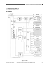
A. Outline ...........................................7-1
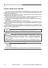
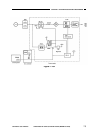
B. Power Supply Circuit Assembly.....7-2
C. Detecting Errors in the Power
Supply PCB ...................................7-4
D. Protection Mechanisms for the
Power Supply Circuit .....................7-5
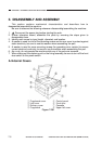
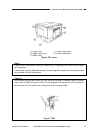
II. DISASSEMBLY AND ASSEMBLY ......7-6
A. External Covers.............................7-6
B. Control Panel.................................7-9
C. Fans...............................................7-10
D. Main Motor/Main Drive Assembly..7-11
E. Cassette unit .................................7-14
F. DC Controller PCB ........................7-17
G. Composite Power Supply PCB......7-18
H. AE Sensor PCB.............................7-21
I. Intensity Sensor PCB ....................7-21
This chapter shows the copier’s external parts, and explains the principles used for the copier’s
various control mechanisms in view of the functions of electrical and mechanical units and in relation
to their timing of operation. It also shows how these units may be disassembled/assembled and
adjusted.
COPYRIGHT
©
1997 CANON INC. CANON NP6218 REV. 0 MAY 1997 PRINTED IN JAPAN (IMPRIME AU JAPON)