


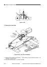
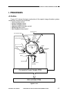
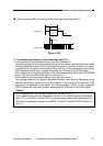
2. Turning On and Off the Scanning Lamp
The microprocessor (Q301) on the DC controller PCB exerts control so that the
microprocessor (Q512) on the composite power supply PCB generates the scanning
lamp ON signal (FLON)=0 (pulse signal, 1 kHz). At the time, the fluorescent lamp drive
circuit applies the output of the secondary side of the transformer (T101) to the scanning
lamp (FL1), thereby allowing current to flow through the scanning lamp and causing the
lamp to turn on at a high frequency (about 120 kHz).
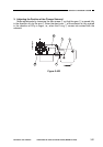
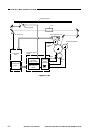
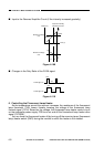
3. Pre-Heating Control (scanning lamp)
The copier exerts four modes of control; namely, half pre-heating, full pre-heating,
ON pre-heating I, and ON pre-heating II.
These modes of control are executed by the microprocessor (Q301) on the DC
controller by varying the duty ratio of the fluorescent lamp pre-heat signal (FLPRHT;
pulse) of 5 kHz to suit each pre-heat control mode sent to each scanning lamp pre-heat
circuit. Based on the signal, the scanning lamp pre-heat circuit modulates the amplitude
of the signal (32 kHz); in response, the secondary side of the transformer (T401) turns
on to allow the fluorescent lamp pre-heat current to flow, thereby starting pre-heating
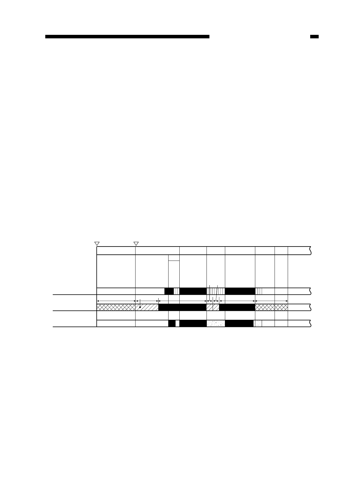
operation. (For the sequence of operations, see Figure 4-105.)
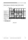
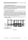
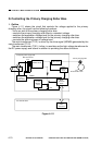
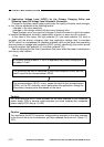
4. Sequence of Operations (scanning lamp pre-heating control; AE, A4,
continuous, 2 copies)
1 half pre-heating control.
2 full pre-heating control.
3 ON pre-heating I or II control.
Figure 4-105
COPYRIGHT
©
1997 CANON INC. CANON NP6218 REV. 0 MAY 1997 PRINTED IN JAPAN (IMPRIME AU JAPON)
CHAPTER 4 IMAGE FORMATION SYSTEM
4-5
STBY
Power switch
ON
Copy Start key
ON
AER
*1*3 *3
*2
*1
*1 *2
INTR SCFW SCRV SCFW SCRV LSTR STBY
Scanner
Scanning lamp
Primary charging
1.5 sec