


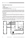

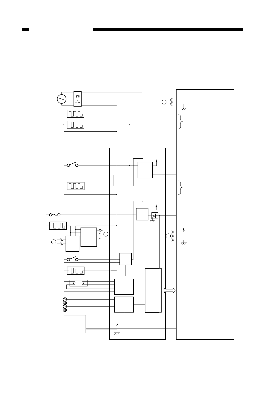
F. Outputs from the DC Controller PCB
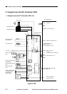
1. Outputs from the DC Controller PCB (1/3)
Figure 2-108
COPYRIGHT
©
1997 CANON INC. CANON NP6218 REV. 0 MAY 1997 PRINTED IN JAPAN (IMPRIME AU JAPON)
CHAPTER 2 BASIC OPERATION
2-8
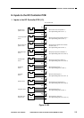
BP102 BP103 BP101
+5V
25V
+5V
+24V
A
B
B
A
RL102
RL101
Q512
HTON*
PWSW*
TEP*
HTRD
EHTRL*
Cassette heater (H4)
Cassette heater (H5)
Anti-condensation
switch (SW1)
Lens heater (R1)
Fuse (FU1)
Fixing heater
(H1)
Fluorescent lamp heater
switch (SW2)
Fluorescent lamp heater
(H2)
Fluorescent lamp
(FL1)
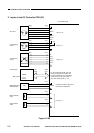
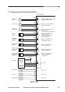
Primary charging roller
Developing cylinder
Transfer roller
Static eliminator
Door switch
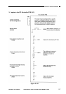
Fixing
heater
driver
Heater
ON
detection
PCB
Toner level
detection
sensor
Thermal
control
circuit
Scanning
lamp control
circuit
High-voltage
circuit
Composite power
supply PCB
Micro-
processor
DC controller PCB
See p. 6-1.
When '0', RL102 turns on
When '0' RL102 turns on.
When L102 turns on,
SW1 turns on,
and heater (R1) turn on.
When '0', RL101
turns on.
(on when power is turned on)
When heater is on, '0'.
Communication with composite
power supply PCB.
When '0',cartridge
indicator turns on.