


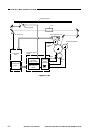
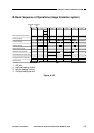
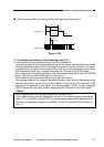
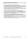

■ Scanning Lamp ON Pre-Heating Control (during copying operation I)
Figure 4-108
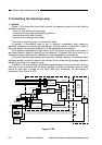
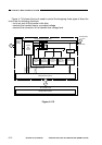
5. Controlling the Intensity of the Scanning Lamp (FL1)
• If the intensity of the fluorescent lamp is too low at power-on,
The starting power of the intensity adjustment sensor lowers, and the fluorescent lamp
intensity adjustment signal (FLS) of the amplifier circuit on the DC controller increases.
In response to the signal, the microprocessor (Q512) on the composite power supply
PCB reduces the duty ratio, thereby increasing the ON time of the FLON signal.
The current flows through the filament of the fluorescent lamp when both the MPWM
signal (150 kHz) and the FLON signal (1 kHz) are on.
• If the intensity of the fluorescent lamp is too high at power-on,
The starting power of the intensity adjustment sensor rises, and the fluorescent lamp
intensity adjustment signal (FLS) of the amplifier circuit on the DC controller PCB
decreases. In response to the signal, the microprocessor (Q512) on the composite
PCB increases the duty ratio, thereby decreasing the ON time of the FLON signal.
Caution:
Gain Adjustment for the Intensity Adjustment Sensor (VR301)
If you replaced the intensity adjustment sensor or the scanning lamp (fluorescent
lamp, FL1), or the DC controller PCB, you must always perform gain adjustment for
the intensity adjustment sensor using VR301 on the DC controller PCB. (See the p.
10-10.)
COPYRIGHT
©
1997 CANON INC. CANON NP6218 REV. 0 MAY 1997 PRINTED IN JAPAN (IMPRIME AU JAPON)
CHAPTER 4 IMAGE FORMATION SYSTEM
4-7
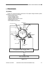
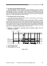
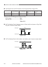
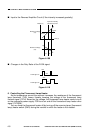
FLON signal
FLPRHT signal
ON ON
5KHz
1KHz
5V
0V
44.4%
OFF OFF
40% or more