


COPYRIGHT
©
1997 CANON INC. CANON NP6218 REV. 0 MAY 1997 PRINTED IN JAPAN (IMPRIME AU JAPON)
CHAPTER 6 FIXING SYSTEM
6-1
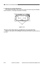
I. BASIC OPERATIONS
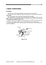
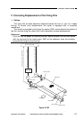
A. Outline
The drive roller of the fixing assembly is driven by the main motor (M1).
When the drive roller rotates, the fixing film rotates and, in conjunction, the pressure
roller rotates.
Part of the inside of the fixing film is heated by the fixing heater.
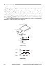
The temperature of the fixing heater is monitored by a thermistor (TH1), and the
result is sent to the microprocessor in the DC controller circuit in the form of the fixing
heater temperature detection signal (TH1).
Based on the result (TH1 signal), the microprocessor on the DC controller varies the
fixing heater drive signal (HTRD) to control the temperature of the fixing heater.
Further, a thermistor (TH2) is also provided on the end (rear) of the fixing heater to
monitor overheating.
Figure 6-101
Drive roller
Delivery roller
Fixing cleaning roller
M1
Pressure roller
Fixing heater
Fixing film
Tension roller
Main motor
Thermistor