


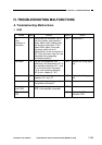
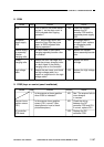
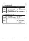
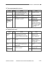

17. DC power supply is absent.
COPYRIGHT
©
1997 CANON INC. CANON NP6218 REV. 0 MAY 1997 PRINTED IN JAPAN (IMPRIME AU JAPON)
10-71
CHAPTER 10 TROUBLESHOOTING
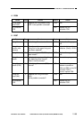
Checks
Is electrical continuity present
between J211-1 on the composite
power supply PCB and J309-1 on
the DC controller PCB?
Replace the control panel.
Cause
Connector
(J211, J302,
J309)
Control panel
DC controller
PCB
Step
10
11
Results
NO
YES
NO
Action
Check the connector
(J302) on the DC
controller PCB; if
normal, replace the DC
controller PCB.
End.
Replace the DC
controller PCB.
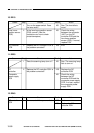
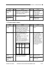
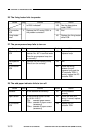
Checks
Is AC power supply present
between the following terminals?
Composite Power Supply PCB
J2-1 (white) and J2-3 (black)
(J2 is the 3-pin connector on the
power supply cord mount.)
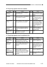
Turn off the power switch, and
disconnect all the following
connectors.
Composite Power Supply PCB
J206, J210
Set the meter to the 20V DC
range, and turn on the power
switch; is the voltage between the
following terminals normal?
Is the fuse of the composite
power supply PCB blown?
Cause
AC power
supply
Wiring, DC load
Fuse
Composite
power supply
PCB
Step
1
2
Results
NO
YES
YES
NO
Action
See “AC power supply is
absent.”
Turn off the power
switch, and connect one
of the disconnected
connectors; then, turn on
the power switch.
Repeat the same on all
connectors to find out
the connector which
activates the protection
circuit; check the wiring
from that connector to
the DC loads.
Replace the fuse.
Replace the composite
power supply.
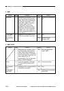
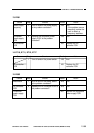
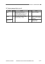
Connector
J206
J210
Pin No.
1
2
1
2
3
4
5
6
Output
34V
GND
24V
GND
5V
GND
34V
GND
Remarksr
to main
motor
driver PCB
DC con
troller PCB