


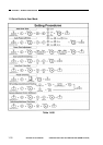
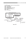
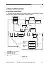
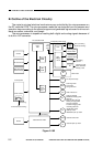
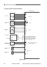

B. Outline of the Electrical Circuitry
The copier’s principal electrical mechanisms are controlled by the microprocessor on
the DC controller PCB. The microprocessor reads the input signals from the sensors and
operation keys according to the stored program and generates signals used to drive such
loads as motors, solenoids, and lamps.
The microprocessor is capable of reading both digital and analog signals because of
its built-in A/D converter.
Figure 2-102
COPYRIGHT
©
1997 CANON INC. CANON NP6218 REV. 0 MAY 1997 PRINTED IN JAPAN (IMPRIME AU JAPON)
CHAPTER 2 BASIC OPERATION
2-2
Sensor
AE sensor PCB
Main thermistor
Sub thermistor
Control panel
Power switch
Control card (accessory)
Sensor
DC controller PCB
Cassette Driver PCB
(accessory)
Composite power supply
High-
voltage
circuit
ADF (accessory)
Sorter (accessory)
Scanning lamp
heater switch
Options
power
supply
Toner level
detection PCB
Bias PCB
Developing
cylinder
Transfer current
Static eliminator
Primary crrent
Main motor
Pre-exposure lamp
Motor
Scanning motor
Lens motor
Fixing film moor
Fan
Heat exhaust fan
Change solenoid
Multifeeder holding plate
solenoid
Blank shutter solenoid
Primary charging roller
Creaning solenoid
Transfer charging roller
reversting solenoid
Registration clutch
Delivery clutch
Multifeeder pick-up clutch
Motor
Cassette unit motor
Cassette pick-up clutch
CL
CL
SL
LA
M1
HV
CPU
Q301
CPU
Q305
ROM
Q307
RAM
Q314
(for IPC
communi-
cation)
+5V
+24V
+34V
(accessory)