


Chapter 2 Operating Principles
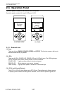
2-2. Operation of Control Parts
2-31 CL-S700/CL-S703/CL-S700R
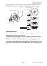
2-2-4. Drivers
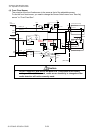
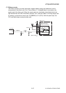
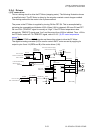
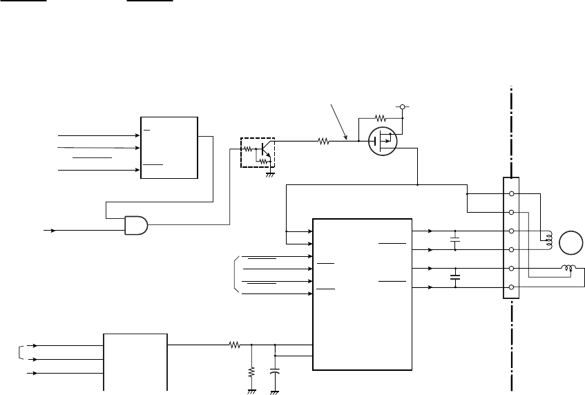
(1) PF motor driver
This is a driving circuit to drive the PF Motor (stepping motor). The following illustration shows
a simplified circuit. The PF Motor is driven by the unipolar constant current chopper method.
The exciting method for the motor is the 2-phase method.
The power to the PF Motor is supplied by turning ON the FET Q4. This is accomplished by
activating the monostable multivibrator U16A. When U16A is triggered, Q5 turns ON and FET
Q4 turns ON. (TEMPOFF signal is normally at “High”. If the PF motor temperature rises
excessively, TEMPOFF signal goes “Low” and the output from U16A is inhibited. Thus, +24V to
the PF Motor is shut off. For TEMPOFF signal, refer to 2-2-3 “(6) PF motor temperature
sensor”.)
PFMA, PFMA, PFMB and PFMB signals are the exciting pulses to drive the PF Motor.
The digital-to-analog converter (U4) is used to control the PF motor current by applying its
output to pins 3 and 14 (REFA and B) of the motor driver (U18).
12
6
7
17
5
16
VSA
VSB
INA
INA
INB
INB
U18
Motor Driver
2
4
1
6
3
J4
OUT A
OUT A
OUT B
OUT B
1
8
11
18
U16A
Monostable
Multivibrator
CLR
A
1
2
B
3
Q
13
Q5
DTC114EM
Q4
XP132A11A1
PFCLK
From U1 CPU
PFON
From U14 Custom IC
GRESET
From U1 CPU
74VHC123
From U14
Custom IC
14
REFA
REFB
C71
R107
R106
PFMOTCU
[Main PCB]
Low: Turns on Q4 to supply
PFMA
PFMA
PFMB
PFMB
3
TMPOFF
1
4
2
U17
5
M
PF Motor
C70
C69
PFMTCOM
From PF Motor Temp.
Sensor Circuit
SLA7033MPR
U4
CSB
10
DI
12
CLK
11
AO1
1
AO2
2
AO3
5
BH2227
DACIN
DACCLK
CS_DAC
From U14 Custom IC
From U1 CPU
power to the PF motor.
+24V
R104
R105