


Chapter 3 Disassembly and Maintenance
3-5. Disassembly, Reassembly and Lubrication
CL-S700/CL-S703/CL-S700R 3-24
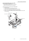
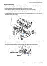
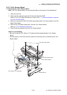
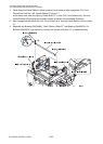
(2) Disassembling the “Unit, Sensor Adjust”
1. Remove the “SA, Sensor U” (Adjustable type) [8-9] and “Shaft, Screw Sensor U” [8-5].
1) Shift the “Cover, Sensor Adjust” [8-2] to the right and remove it upwardly.
Peel off the “Open Guide Seal” [8-1] from the “Cover, Sensor Adjust” [8-2].
2) On the right side, disengage 1 E-ring (E-Ring, 2) [8-28], shift the “Shaft, Screw Sensor
U” [8-5] to the left about 2 mm (0.08”), and remove the block (consisting of “Shaft,
Screw Sensor U” [8-5] and “SA, Sensor U” (Adjustable type) [8-9], etc.) to the right.
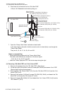
3) Peel off Position Label [8-6], remove 2 screws (No. 0, FHT (BT#1), M2x4) [8-27],
Stopper Plate [8-7] and Move Pin [8-8] from the “SA, Sensor U” (Adjustable type) [8-9].
4) Cut the Wire Tie [8-10].
5) Pull out the “SA, Sensor U” (Adjustable type) [8-9] from the “Shaft, Screw Sensor U”
[8-5].
6) Disengage 1 E-ring (E-Ring, 3) [8-26], pull out the “Pin, Teeth Spring 1.2x8” [8-3], and
remove the Screw Gear [8-4] to the left from the “Shaft, Screw Sensor U” [8-5].
Notes on reassembling:
• Do not reuse the “Pin, Teeth Spring 1.2x8” [8-3].
• Apply grease (Floil G-311S) to the “Shaft, Screw Sensor U” [8-5] at 3 places (marked
with in Drawing No. 8 “Unit, Sensor Adjust” for the Printer Part in Chapter 5 “Parts
List”).
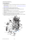
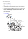
2. Remove the “SA, Sensor Bottom” (Adjustable type) [8-24] and “Shaft, Screw Sensor L”
[8-23].
1) Remove 1 screw (PH (SW+PW), M3x5) [8-29] and detach the Ratchet Spring [8-31].
2) On the right side, disengage 1 E-ring (E-Ring, 3) [8-26], shift the “Shaft, Screw Sensor
L” [8-23] to the left about 2 mm, and remove the block (consisting of “Shaft, Screw
Sensor L” [8-23] and “SA, Sensor Bottom” (Adjustable type) [8-24], etc.) to the right.
3) Cut the Wire Tie [8-10].
4) Pull out the “SA, Sensor Bottom” (Adjustable type) [8-24] from the “Shaft, Screw
Sensor L” [8-23].
5) Disengage 1 E-ring (E-Ring, 3) [8-26], pull out the “Pin, Teeth Spring 1.2x8” [8-3], and
remove the Screw Gear [8-4] to the left from the “Shaft, Screw Sensor L” [8-23].
Also, remove the Ratchet Gear [8-19] from the “Shaft, Screw Sensor L” [8-23], after
pulling out the “Pin, Teeth Spring 1.2x8” [8-3].
Notes on reassembling:
• Do not reuse the “Pin, Teeth Spring 1.2x8” [8-3].
• Apply grease (Floil G-311S) to the “Shaft, Screw Sensor L” [8-23] at 3 places (marked
with in Drawing No. 8 “Unit, Sensor Adjust” for the Printer Part in Chapter 5 “Parts
List”).
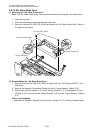
3. Remove the Open Guide Lever [8-12].
1) Disengage 1 E-ring (E-Ring, 2) [8-28] and remove the Open Guide Lever [8-12] and
Open Guide Lever Spring [8-13].
4. Remove the Paper Guide Plate [8-14].
1) Remove 2 screws (PH, M3x3) [8-30] and detach the Paper Guide Plate [8-14].