


Chapter 3 Disassembly and Maintenance
3-5. Disassembly, Reassembly and Lubrication
CL-S700/CL-S703/CL-S700R 3-18
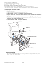
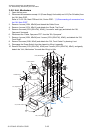
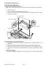
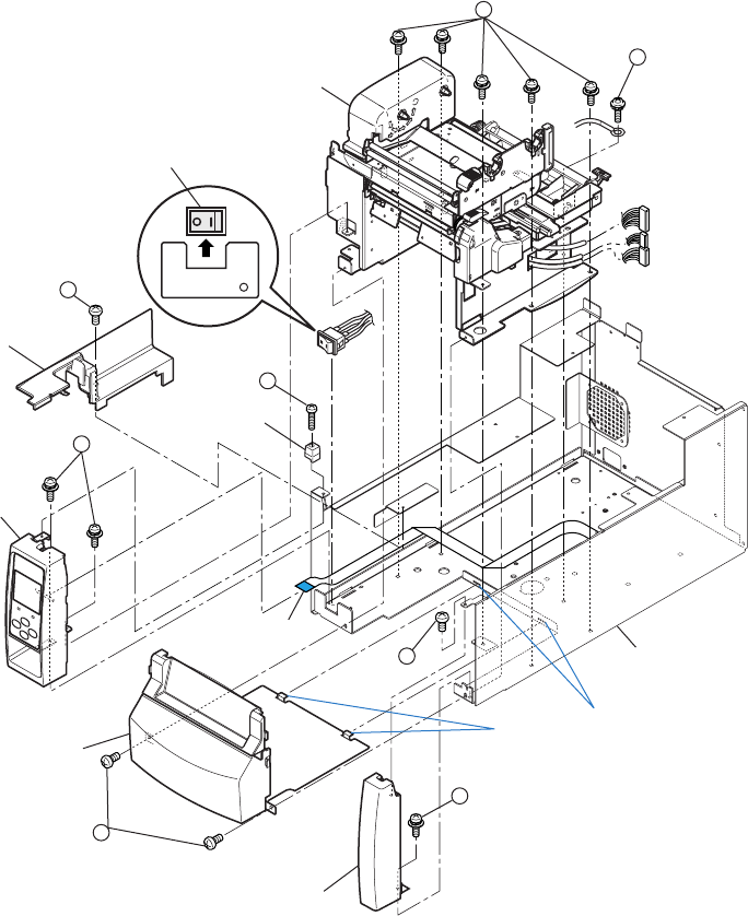
3-5-8. Unit, Mechanism
1. Open the top cover.
2. Disconnect all connectors except J11 (Power Supply Unit cable) and J12 (Fan SA cable) from
the “SA, Main PCB”.
Refer to “3-5-5. SA, Main PCB and Unit, Centro PCB” - “(1) Disconnecting all connectors from
the “SA, Main PCB””.
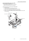
3. Remove 1 screw (1BH, M3x5K) and detach the Cable Cover.
4. Remove 1 screw (2PH, M3x12) and detach the “Guide, Top Cover”.
5. Remove 2 screws (3PH (SW+PW), M3x5) (1 screw for new type) and detach the “SA,
Ope-pane” frontward.
6. Disconnect the “Cable, Ope-pane FFC” from the “SA, Ope-pane”.
7. Remove 1 screw (4BH, M3x5K) and 1 screw (5PH (SW+PW), M3x5), and detach the “SA,
Front Right”.
8. Remove 2 screws (6BH, M3x5) and detach the “SA, Front Center” by drawing it out.
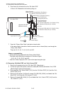
9. Disengage the Power Switch from the chassis by lifting it upwardly.
10. Remove 5 screws (7PH (SW+PW), M3x5) and 1 screw (8PH (SW+PW), M3x5), and gently
detach the “Unit, Mechanism” forward after lifting it a little.
2
1
3
5
6
7
8
Unit, Mechanism
Power Switch
Cable Cover
Guide, Top Cover
SA, Ope-Pane
Cable, Ope-Pane
FFC
SA, Front Right
SA, Front Center
4
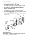
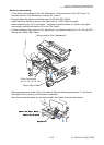
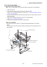
J3
J12
J15
A
SA, Case L
B