


Chapter 2 Operating Principles
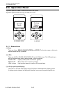
2-2. Operation of Control Parts
2-33 CL-S700/CL-S703/CL-S700R
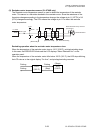
Thermal resistance check:
When the printer is turned ON, the thermal resistance check is conducted. If any fault is found,
the ERROR LED blinks and the LCD displays “Alarm Head Check” on the operation panel.
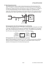
During the thermal resistance check, pin 117 (HCVON) of U14 (Custom IC) goes to "High", and
Q29 and Q3 turn ON. Thus, +3.3V is supplied to the thermal head, instead of +24V.
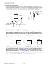
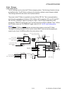
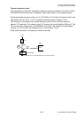
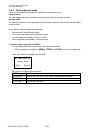
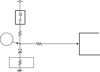
The following is a simplified circuitry under checking, where Q3 turns ON and a thermal
element "R" is selected. The voltage at point “A” becomes the value divided by R99 and R. The
CPU monitors this voltage at pin 10 (HEADRES), and check if the voltage is in the allowable
range or not. (If R is open, the voltage at point “A” will be about +3.3V.)
Every thermal element is successively checked in this way.
+3.3V
U1
CPU
R99
R
A
R: Resistance of a thermal element in the thermal head
Q3
Thermal head
R100
HEADRES
ANI5
10
D2