


Chapter 3 Disassembly and Maintenance
3-5. Disassembly, Reassembly and Lubrication
3-17 CL-S700/CL-S703/CL-S700R
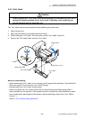
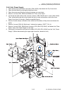
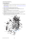
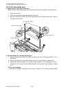
3-5-6. SA, Fan
1. Disconnect J12 (for “SA, Fan”) from the “SA, Main PCB”.
Refer to “3-5-5. SA, Main PCB and Unit, Centro PCB” - “(1) Disconnecting all connectors from
the “SA, Main PCB””.
2. Remove the “Plate, Power” [1-14] (together with “Unit, Power Supply”).
Refer to “3-5-4. Unit, Power Supply.
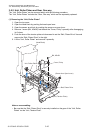
3. Remove 4 screws (PH (SW+PW), M4x30) [1-40] and detach the “SA, Fan” [1-20].
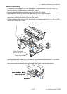
Notes on reassembling:
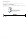
• Assemble the “SA, Fan” [1-20] so that its cable runs from the right bottom side as shown in
Drawing 1 “General Assembly” in Chapter 5 “Parts List” (the label of “SA, Fan” will face
backward). In this direction, air flows from inside to outside.
• When assembling the “Plate, Power” [1-14] (together with “Unit, Power Supply”), observe the
“Notes on reassembling” in “3-5-4. Unit, Power Supply.
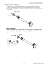
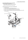
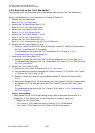
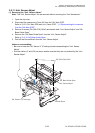
3-5-7. SA1, Top Cover
1. Open the top cover.
2. Remove 2 screws (BH, M3x5K) [1-39] and detach the 2 “Cover, Hinge” [1-4] from the top cover
by releasing their claws.
3. Remove 4 screws (BH, M3x5) [1-37] and detach the Top Cover block from the printer.
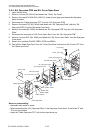
4. Remove 4 screws (BH, M3x5) [1-37] and detach the 2 “Stopper, Hinge” [1-8] and the “SA,
Hinge” [1-9] from the “Unit, Top Cover” [1-3].
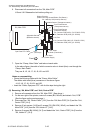
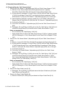
5. Remove 2 screws (PHT (#2), M3x6) [10-6] and remove the Front Top Cover block from the
“SA1, Top Cover” [10-1].
6. Pull out the “Cover, Cutter Blind” [10-4] and take off the “Logo, CITIZEN” [10-3] from the “Cover,
Front Top” [10-2].
7. Remove the “Cover, Window” [10-5] and 4 “Spacer Leg, Case U” [10-7] from the “SA1, Top
Cover” [10-1].