


Chapter 3 Disassembly and Maintenance
3-5. Disassembly, Reassembly and Lubrication
CL-S700/CL-S703/CL-S700R 3-16
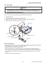
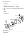
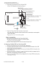
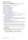
6. Disconnect all connectors from the “SA, Main PCB”.
J15 and J16: Release the lock before pulling out.
7. Open the “Clamp, Main Cable” and take out each cable.
In the above figure, the cable of which connector color is tinted (blue) runs through the
“Clamp, Main Cable”.
They are J4, J5, J6, J7, J8, J9, J21 and J22.
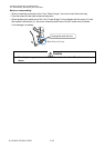
Notes on reassembling:
• Clamp the following cables with the “Clamp, Main Cable”.
The cables with tinted (blue) connectors in the above figure:
J4, J5, J6, J7, J8, J9, J21 and J22.
• Insert the “Cable, Ope-pane FFC” with its blue tape facing the right.
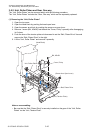
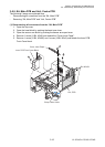
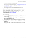
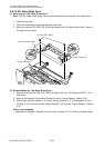
(2) Removing “SA, Main PCB” and “Unit, Centro PCB”
1. Remove all connectors from the “SA, Main PCB”. (See above.)
2. On the rear right of the printer, remove 3 screws (BH, M3x5K) and detach “Unit, PCB”.
(See the figure on the previous page.)
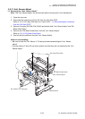
3. Disconnect the “SA, Centro Cable” [14-1] from the “SA, Main PCB” [14-2] and the “Unit,
Centro PCB” [14-4].
4. Remove 2 lock screws [14-5] and 2 screws (PH (SW+PW), M3x5), and detach the “SA,
Main PCB” [14-2] from the “SA, Holder I/F” [14-3].
5. Remove 2 screws (BH, M3x5) [14-7] and detach the “Unit, Centro PCB” [14-4] from the
“SA, Holder I/F” [14-3].
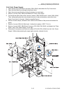
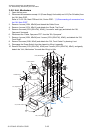
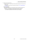
J16
J12
J6
J21
J7
J22
J11
J5
J4
J15
J3
J14
J9
J8
Front
SA, Main PCB
Ribbon Encoder
(Ribbon Running Sensor/Ribbon End Sensor)
SA, Head Up SW (Head Up Sensor)
Adjustable Sensor (Transparent sensor)
Front Fixed Sensor
(Transparent sensor)
Adjustable Sensor
(Reflective sensor)
Front Fixed Sensor
(Reflective sensor)
SA, Connect PCB (J801) (CL-S700/CL-S703)
SA, Rewinder PCB (J501) (CL-S700R)
SA, Fan
Unit, Head
Unit, Motor
Unit, Motor (Thermistor)
Unit, Power Supply
Ope-Pane FFC Cable
(Blue Tape)
SA, Connect PCB (J803) (CL-S700/CL-S703)
SA, Rewinder PCB (J502) (CL-S700R)