Chapter 2 Operating Principles
2-2. Operation of Control Parts
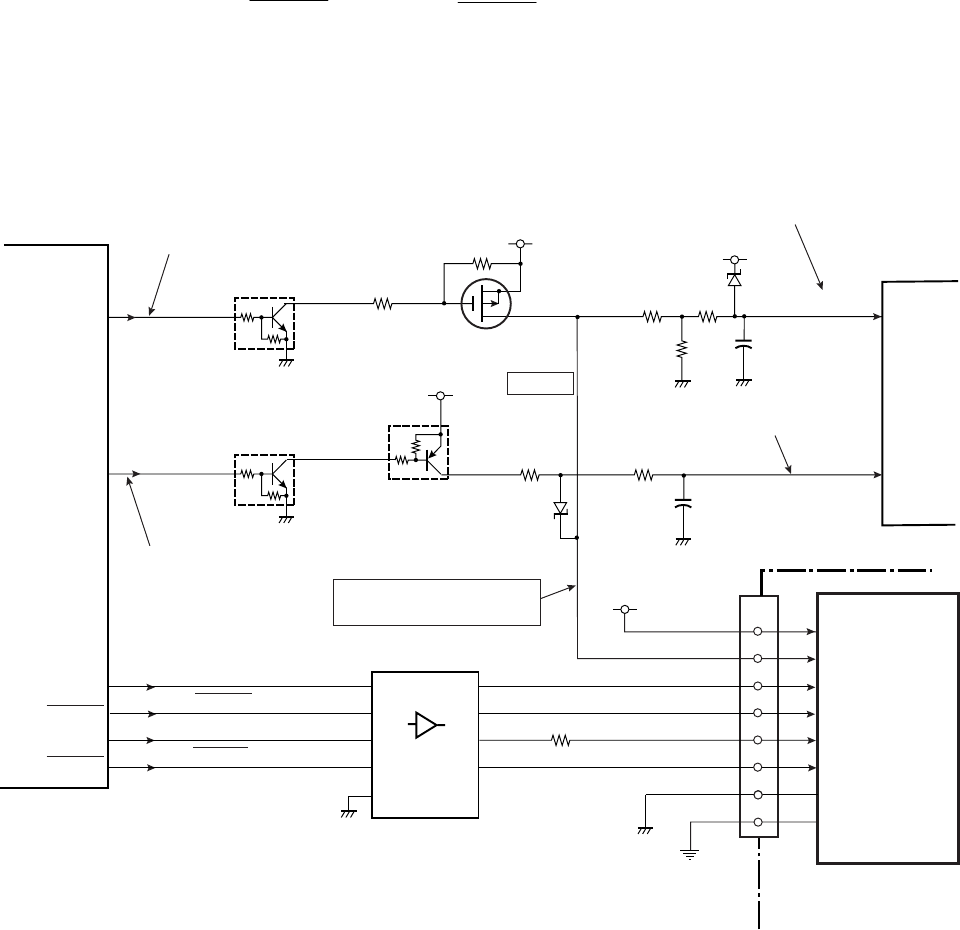
CL-S700/CL-S703/CL-S700R 2-32
(2) Head driver
The head driver is incorporated in the “Unit, Head”.
During printing, pin 116 (HDVON) of U14 (Custom IC) goes to "High", and Q2 and Q1 turn ON.
Thus +24V is supplied to the thermal head (“Unit, Head”).
The print data is sent from U14 (Custom IC) to the head driver in the thermal head.
The signals HD1 to 4, HDSTB, HDCLK and HDLAT (pins 109 to 113, 108, 115 and 107 of U14)
are sent to the thermal head.
According to the print data (HD1 to 4), the selected thermal elements are heated and the
melted ink makes dots on media (or dots are printed on thermal transfer paper).
The width of heating pulse applied to a thermal element varies with the head temperature to
keep the printing density constant.
J3
Thermal
Head
5-8,21-25
1-4,26-30
HEADSTB
HEADCLK
HEADD1-4
HEADLAT
+5V
10,12,14,17
13
U14
Custom IC
HDLTH
107
HDSTB
108
HDCLK
115
HDATA1-4
109-113
HDVON
HCVON
HDVON
116
HCVON
117
+24V
R93
R94
Q1
Q2
Q29
R99
VHEAD
DTC114EM
D2
2SJ505S
D1
+3.3V
U1 CPU
R100
R95
R97
R96
Head supply voltage ON/OFF
Thermal element abnormality check ON
Head power supply monitoring
Thermal element abnormality check
[Main PCB]
When driving: +24V
When checking: +3.3V
HD1-4
HDSTB
HDCLK
HDLAT
16
11
13
2,4,6,8
5
9
7
18,16,
14,12
16
18
9,15
Q3
+3.3V
DTA114EM
DTC114EM
C61
C62
74HCT244
1,19
R101
11
HDTHM1
VHEADMON
HEADRES
ANI4
9
ANI5
10
A1-4
Y1-4
A5
Y5
A6 Y6
A7 Y7
U15A
OE


