MIL-3000FTX Series of FastPort Print Servers 1-4
1.7 Installing FastPort
Do the following to physically install the MIL-3000FTX series of FastPort
printer servers. Contact Digi’s LAN technical support if you have
problems or questions when installing the print server (see Appendix I).
1. Attach the Rubber feet to the bottom of the print server. Place one on
each corner of the device.
2. Record the Ethernet address (located on the bottom of the unit) for
future reference.
3. Attach the Ethernet cabling. The MIL-3000FTX supports 10/100BASE-
TX and has an RJ-45 connector. Use CAT 5 (UTP).
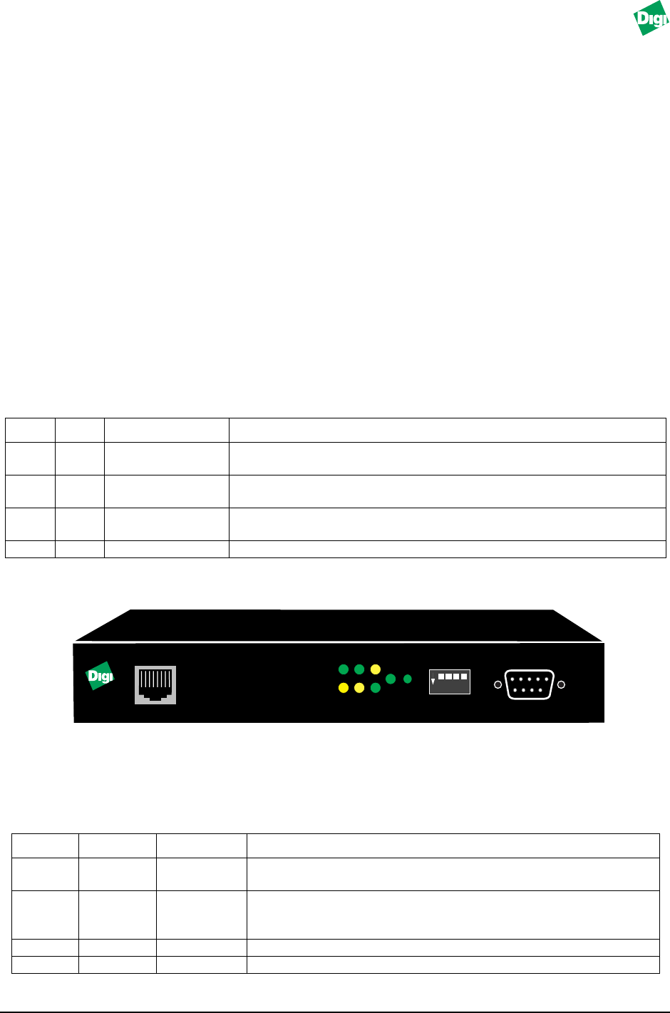
4. Select an operating mode with the front panel switches. Use Table 1-1.
Table 1-1: Operating Mode
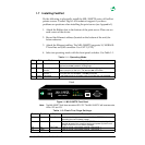
Figure 1-1. MIL-3100FTX Front Panel
Note:
The MIL-3200FTX will have one extra LED: “P2.” The MIL-3310FTX will have two extra
LEDs: “P2” and “P3.”
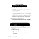
Table 1-2: Flash/Test Page Settings
D3 D4 Mode Description
Up
Up Normal Does not allow a telnet session. Users can print to the unit. The
SYS
(system) and
NET
(network) LEDs blinks.
Down Up Telnet diagnostic
monitor
Allows a telnet session to monitor FastPort or change its parameters.
Users can print to the unit. The
SYS
and
NET
LEDs blink.
Down Down Serial diag.
monitor
A terminal can be attached to the serial port to run a serial monitor.
Print jobs are not accepted. The
NET
LED blinks.
Up Down Test page A test page prints on a power cycle. Print jobs are not accepted.
Switch
Position Mode Description
D1
Up Flash Bank Selects bank 0 (upper) to run the 4 Mb Flash EEPROMs for
uploading the new firmware image.
D1 Down Selects bank 1 to run the 4Mb flash EEPROMs for uploading. If the
upgrade process fails, use this setting and power cycle the unit
to return FastPort to its default settings.
D2 Up Test Page FastPort prints a test page: parallel 2 and serial 1.
D2 Down FastPort prints a test page: parallel 1 and serial 1.
MIL•3100FTX
FastPort 10/100 Mb/s
PRINT SERVER
Front
ON
1 2 3 4
10/100
RX TX P1
LNK NET SYS SER PWR
SWITCH
SERIAL


