


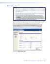
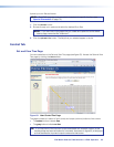
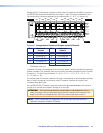
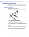
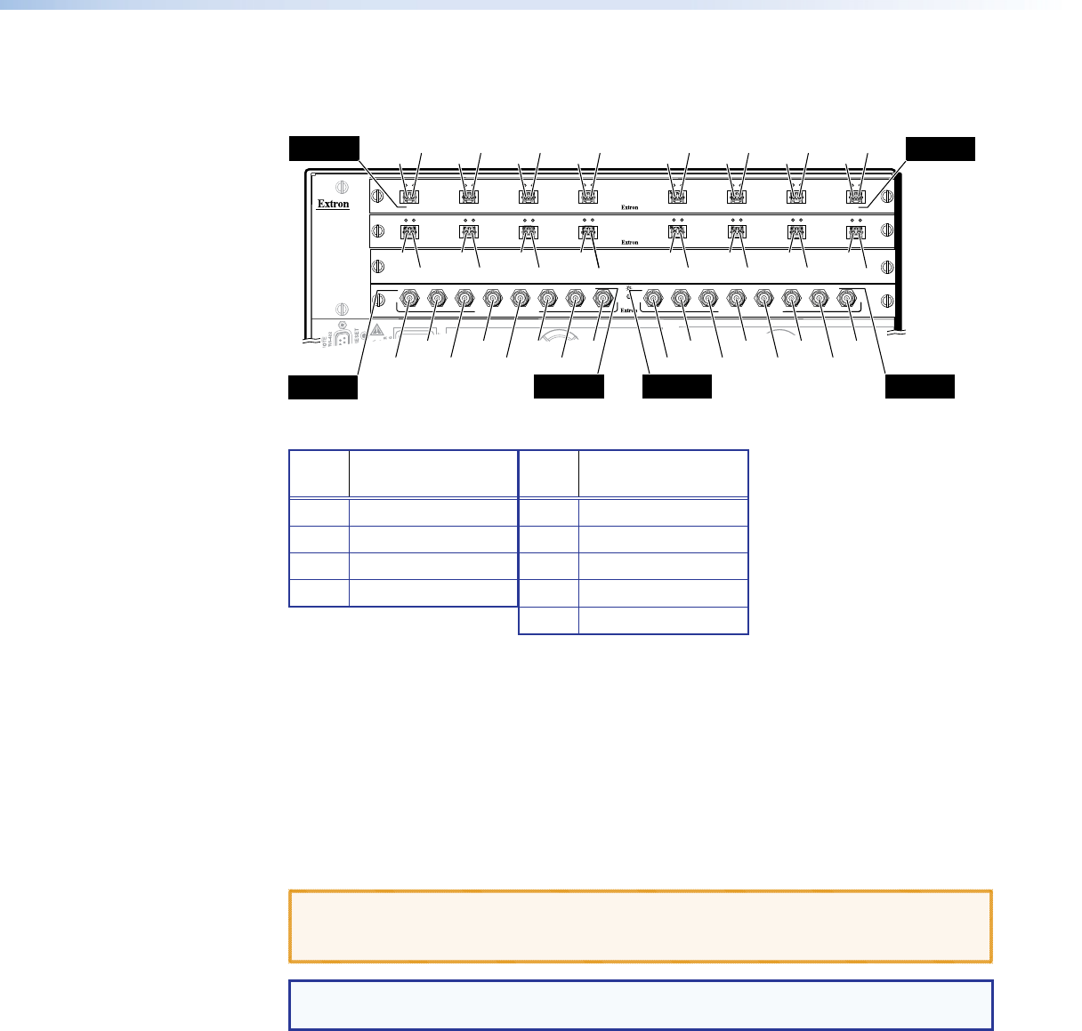
See figure 64. The transceiver modules on fiber optic I/O boards and the BNC connectors
on SDI/HD‑SDI boards are identified as A through H . Each I/O board is identified by the
input and output numbers supported by the board position (1 ‑ 8, 9 ‑ 16, and so on).
ANAHEIM, CA
100-240V 50/60Hz 1.2A MAX.
PRIMARY POWER SUPPLY
REDUNDANT POWER SUPPLY
1 - 8
9 - 16
17 - 24
A
B
C
D
E
F
OUT
IN
OUT
IN
OUT
IN
OUT
IN
OUT
IN
OUT
IN
A
B
C
D
E
F
G
H
OUT
IN
OUT
IN
OUT
IN
OUT
IN
OUT
IN
OUT
IN
OUT
IN
OUT
IN
25 - 32
MUTI-RATE SDI INPUTS
H
G
AD
E
F
C
B
MUTI-RATE SDI OUTPUTS
H
G
D
E
F
C
G
H
OUT
IN
OUT
IN
H
G
AD
E
F
C
B
Location
A
Input
Location H
Output
Location H
Output and Input
Location A
Output and Input
Slot 1
(1-8)
O#1
I#1
Slot 2
(9-16)
Slot 3
No board
installed
Slot 4
(25-32)
O#2
I#2
O#3
I#3
O#4
I#4
O#9
I#25
I#26
I#27
I#28
I#29
I#30
I#31
I#32
O#25
O#26
O#27
O#28
O#29
O#30
O#31
O#32
I#9
O#10
I#10
O#11
I#11
O#12
I#12
O#5
I#5
O#6
I#6
O#7
I#7
O#8
I#8
O#13
I#13
O#14
I#14
O#15
I#15
O#16
I#16
H
Location A
Output
Location H
Input
Figure 64. Arrangement of Inputs and Outputs on the I/O Boards
Slot Inputs and
outputs
Slot Inputs and
outputs
1 1 through 8 5* 33 through 40
2 9 through 16 6* 41 through 48
3 17 through 24 7* 49 through 56
4 25 through 32 8* 57 through 64
9* 65 through 72
* FOX Matrix 7200 only
Locations A through H correspond to the input and output numbers identified by the board
position numbers. (For example, the input and output numbers supported by the I/O board
in location 9 ‑ 16 (slot 2) are as follows: A = 9, B = 10, C = 11, D = 12, E = 13, F = 14,
G = 15, and H = 16.)
On the fiber optic I/O boards, locations A through H correspond to the transceiver modules,
each of which includes an input and an output. Therefore, locations A through H are
numbered from left to right.
On the SDI/HD‑SDI I/O boards, inputs and outputs are grouped separately, with inputs A
through H on the left and outputs A through H on the right.
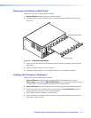
ATTENTION: Do not touch the electronic components or the backplane or circuit
board connectors without being electrically grounded. Handle circuit boards by their
edges only. ESD can damage circuits, even if you cannot feel, see, or hear it.
NOTE: The I/O boards are hot‑swappable. You do not need to power down the
switcher to remove or install an I/O board.
FOX Matrix 3200 and 7200 Switchers • Maintenance and Modifications 111