


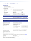
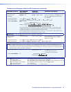
Command and Response Table for SIS Commands
Symbol Definitions
] = CR/LF (carriage return/line feed) (hex 0D 0A)
} = Carriage return (no line feed, hex 0D)
| = Pipe (can be used interchangeably with the } character)
• = Space character
E = Escape key (hex 1B)
W = Can be used interchangeably with the E character
X! = Input number (for tie) 00 – 32 (FOX Matrix 3200) or 72 (FOX Matrix 7200) (00 = untied)
X@ = Output number 01 – 32 (FOX Matrix 3200) or 72 (FOX Matrix 7200)
X# = Mute 0 = not muted 1 = muted
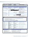
X$
= SFP or reclockable output number 00 – 32 or 72 (00 = global [SFP only])
X% = Output reclocking rate 00 = auto (default) 01 = bypass
X^ = Laser control 0 = disable 1 = enable 2 = automatic
X& = Global preset # 00 – 32 (3200) or 72 (7200) (00 = current configuration for view only)
X* = Room number (for room presets) 01 – 10 maximum (each can have up to 10 presets (X1)) assigned)
NOTE: A Room is a subset of operator‑selected outputs that relate to each other. The FOX matrix switcher supports up to 10 rooms, each
of which can consist of 1 to 16 outputs.
X( = Name Up to 12 characters for input and output names and global and room preset names
Upper‑ and lower‑case alphanumeric characters and _ / and spaces are valid.
NOTE: The following characters are invalid or not recommended in the name:
~ , @ = ‘ [ ] { } < > ’ “ ; : | \ and ?
.
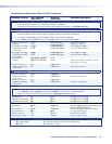
X1) = Room preset number 01 – 10 maximum
NOTE: A Room preset is a stored configuration with all outputs in a single room. A retrieved room preset becomes the current configuration.
X1! = Connection status 0 = no input connected 1 = input connected
X1@ = Group number (for I/O grouping) 1 (group 1) through 4 (group 4) (or 0 = no group)
X1# = Input number (for other than tie) 01 – 32 (FOX Matrix 3200) or 72 (FOX Matrix 7200)
X1$ = Lock mode status 0 = unlocked 1 = locked
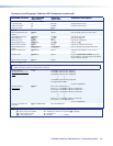
X1% = Number (quantity) of inputs 8, 16, 24, 32, 40, 48, 56, 64, or 72
X1^ = Number (quantity) of outputs 8, 16, 24, 32, 40, 48, 56, 64, or 72
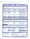
X1&
= Board installed 0 = No board installed 4 = Non‑pathological multimode board
1 = Non‑reclocking multimode board* 5 = Non‑pathological singlemode board
2 = Non‑reclocking singlemode board* 6 = Pathological singlemode board
3 = 3G, SDI, HD‑SDI board x = Unknown board or mix of transceivers
X1* = I/O board slot number 1 – 9 (FOX Matrix 7200) or 1 – 4 (FOX Matrix 3200)
X1( = Transceiver module installed 0 = No module installed
1 = Non‑pathological multimode module 3 = 3G‑SDI, HD‑SDI, SD‑SDI module
2 = Non‑pathological singlemode module 4 = Pathological singlemode module
X2) = Transceiver module number 01 – 72 (or maximum number of transceiver modules for your configuration)
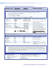
X2! = Vendor/manufacturer name
X2@ = Transmit output power in milliwatts
X2# = Receive optical power in milliwatts
X2$ = SFP temperature Degrees Celsius
X2% = Firmware version number to second decimal place (x.xx)
X2^ = Verbose firmware version‑description‑upload date/time. See the Query controller firmware version (verbose) command on page 65.
X2& = Voltage Positive or negative voltage and magnitude
X2* = Temperature Degrees Fahrenheit
X2( = Fan speed In revolutions per minute (RPM)
* Legacy board, no longer manufactured, identified for completeness only
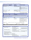
X1) = Output rate: nnnn = actual rate (in MHz) 0000 = no connection or rate
mismatch
‑ ‑ ‑ ‑ = bypass mode
X2@ = Reclocking status 0 = Signal reclocked 1 = Signal not reclocked
X2@
= Reclocking status 0 = Signal reclocked 1 = Signal not
reclocked
FOX Matrix 3200 and 7200 Switchers • Programming Guide 58