


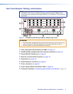
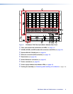
I/O Boards
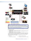
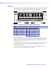
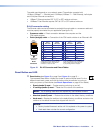
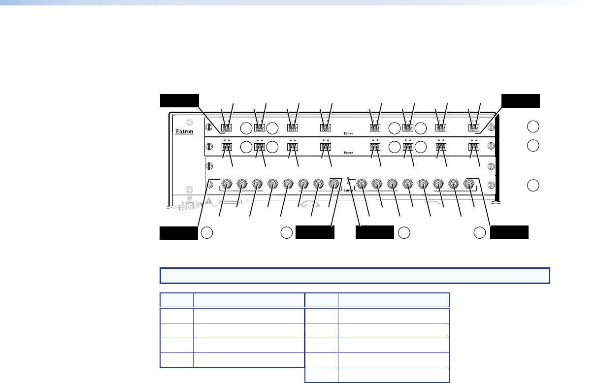
As shown in figure 5, each I/O board is identified by the input and output numbers supported
by the board position, which are printed on the side of each fan module (1 ‑ 8, 9 ‑ 16, and
so on). The transceiver modules on fiber optic I/O boards are identified as A through H.
ANAHEIM, CA
100-240V 50/60Hz 1.2A MAX.
PRIMARY POWER SUPPLY
REDUNDANT POWER SUPPLY
1 - 8
9 - 16
17 - 24
A
B
C
D
E
F
OUT
IN
OUT
IN
OUT
IN
OUT
IN
OUT
IN
OUT
IN
A
B
C
D
E
F
G
H
OUT
IN
OUT
IN
OUT
IN
OUT
IN
OUT
IN
OUT
IN
OUT
IN
OUT
IN
25 - 32
MUTI-RATE SDI INPUTS
H
G
AD
E
F
C
B
MUTI-RATE SDI OUTPUTS
H
G
D
E
F
C
G
H
OUT
IN
OUT
IN
H
G
AD
E
F
C
B
Location
A
Input
Location H
Output
Location H
Output and Input
Location A
Output and Input
Slot 1
(1-8)
O#1
I#1
Slot 2
(9-16)
Slot 3
No board
installed
Slot 4
(25-32)
O#2
I#2
O#3
I#3
O#4
I#4
O#9
I#25
I#26
I#27
I#28
I#29
I#30
I#31
I#32
O#25
O#26
O#27
O#28
O#29
O#30
O#31
O#32
I#9
O#10
I#10
O#11
I#11
O#12
I#12
O#5
I#5
O#6
I#6
O#7
I#7
O#8
I#8
O#13
I#13
O#14
I#14
O#15
I#15
O#16
I#16
H
Location A
Output
Location H
Input
1
2a 2a
1a 1b 1a 1b
1a 1b 1a 1b
2b 2b
1
2
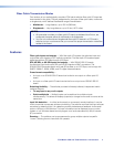
Figure 5. Arrangement of Inputs and Outputs on the I/O Boards
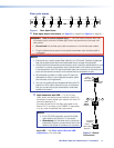
NOTE: The output on the transceiver module is to the left of the input.
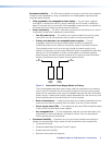
Slot Inputs and Outputs Slot Inputs and Outputs
1 1 through 8 5* 33 through 40
2 9 through 16 6* 41 through 48
3 17 through 24 7* 49 through 56
4 25 through 32 8* 57 through 64
9* 65 through 72
* FOX Matrix 7200 only
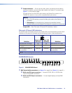
Locations A through H correspond to the input and output numbers identified by the board
position numbers. For example, the input and output numbers supported by the I/O board
in location 9 ‑ 16 (slot 2) are as follows: A = 9, B = 10, C = 11, D = 12, E = 13, F = 14,
G = 15, and H = 16.
On the fiber optic I/O boards, locations A through H correspond to the transceiver modules,
each of which includes an input and an output. Therefore, locations A through H are
numbered from left to right.
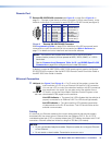
On the SDI/HD‑SDI I/O boards, inputs and outputs are grouped separately, with inputs A
through H on the left and outputs A through H on the right.
FOX Matrix 3200 and 7200 Switchers • Installation 10