


ANAHEIM, CA
RESET
REMOTE
RS-232/RS-422
LAN
BI-LEVEL
TRI-LEVEL
ACT LINK
100-240V 50/60Hz 1.2
A MAX.
100-240V 50/60Hz 1.2A MAX.
REDUNDANT
PRIMARY
DISCONNECT BOTH POWER
CORDS BEFORE SERVICING
SWITCH
REFERENCE
PRIMARY POWER SUPPLY
REDUNDANT
POWER SUPPLY
1 - 8
A
B
C
D
E
F
G
H
OUT
IN
OUT
IN
OUT
IN
O
UT
IN
O
UT
IN
O
U
T
IN
O
UT
IN
O
UT
IN
OUT
9 - 16
A
B
C
D
E
F
G
H
OUT
IN
OUT
IN
OUT
IN
O
UT
IN
O
UT
IN
OU
T
IN
O
UT
IN
O
UT
IN
OUT
17 - 24
A
B
C
D
E
F
G
H
OUT
IN
OUT
IN
OUT
IN
OUT
IN
O
UT
IN
O
UT
IN
OUT
IN
OU
T
IN
OUT
25 - 32
A
B
C
D
E
F
G
H
OUT
IN
OUT
IN
OUT
IN
O
UT
IN
OU
T
IN
OUT
IN
O
UT
IN
O
UT
IN
OUT
50/60 Hz
100-240V 0.3A
R
/R-Y
R
/R-Y
I
N
P
U
T
S
O
U
T
P
U
T
S
G
/Y
2
RGB/R-Y, B-Y, Y
RGB
1
G-Y
B
/B-Y
B
/B-Y
H
/HV
H
/HV
V
V
VIDEO
S-VIDEO
D1
R/R-Y
G/Y
B/B-Y H/H-Y
RS-232
/422
G
E
N
L
O
C
K
V
IN
OUT
V
Extr
on
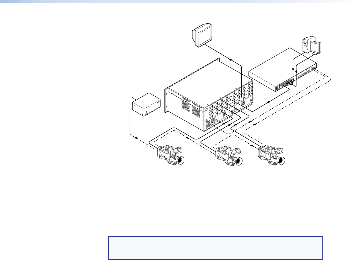
BBG 6
A
Blac
kburst/Color Bars/
A
udio Generator
SDI/HD-SDI
Video Camera
SDI/HD-SDI
Monitor
Extron
FOX Matrix 3200
Matrix Switcher
SDI/HD-SDI
Video Camera
SDI/HD-SDI
Video Camera
VGA Input
Extron
VSC 900D
Computer-to-Video
Scan Converter
(SDI only)
DISTRIBUTION AMPLIFIER
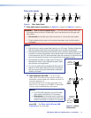
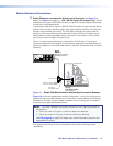
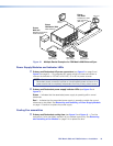
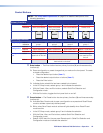
Figure 12. Multiple Device Example of a FOX Matrix 3200 External Sync
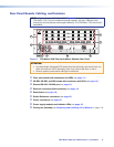
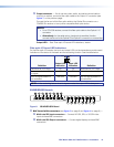
Power Supply Modules and Indicator LEDs
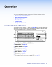
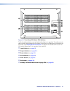
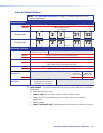
g Primary and Redundant AC power connectors (see figure 3 on page 8 and
figure 4 on page 9) — Plug standard IEC power cords into these connectors to
connect the switcher to 100 VAC to 240 VAC, 50 or 60 Hz power sources.
NOTE: For the most reliable power, connect the power cord from the
Redundant power connector to either an uninterruptible power source or to a
power source that is completely independent from the primary power source.
h Primary and Redundant power supply indicator LEDs (see figure 3 and
figure 4) —
Green — Indicates that the associated power supply is operating within normal
tolerances.
Red — Indicates that the associated power supply is operating outside the normal
tolerances or has failed. See Removing and Installing a Power Supply Module
on page 113 section to replace the power supply.
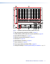
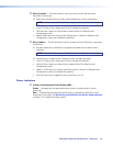
Cooling Fan assemblies
i Primary and Redundant cooling fans (see figure 3 and figure 4) — Cool the
equipment. If a fan has failed, replace it at your earliest opportunity. See Removing
and Installing a Fan Module on page 114 to replace the fans.
FOX Matrix 3200 and 7200 Switchers • Installation 16