


Front Panel Configuration Port
FOX 4G MATRIX 3200
FIBER OPTIC DIGITAL MATRIX SWITCHER
POWER SUPPLY
PRIMARY
REDUNDANT
CONTROL
CONFIG
ENTER PRESET
VIEW
ESC
1
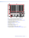
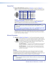
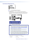
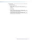
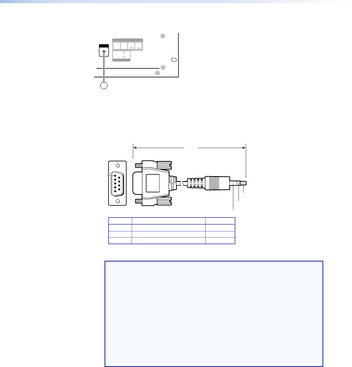
Figure 13. Front Panel Configuration (Config) Port
a Configuration port — This 2.5 mm mini stereo jack serves the same serial
communications function as the rear panel Remote port, but it is easier to access
than the rear port after the matrix switcher has been installed and cabled. The optional
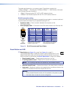
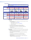
9‑pin D to 2.5 mm mini jack TRS RS‑232 cable (see figure 14) can be used for this
connection.
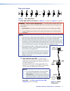
6 feet
(1.8 m)
5
1
9
6
Sleeve
(Gnd)
Ring
Tip
9-pin D Connection TRS Plug
Pin 2 Rx line on the computer Tip
Pin 3 Tx line on the computer Ring
Pin 5 Signal ground on the computer Sleeve
Figure 14. Optional 9-pin TRS RS-232 Cable
NOTES:
• This port is independent of the rear panel Remote port and is not affected by
changes to the protocol of the rear panel port. The protocol of the front panel
port can be changed under SIS command control only. See the Command
and Response table for IP- and SNMP-Specific SIS commands on
page 68 to configure this port under SIS control.
• A front panel Configuration port connection and a rear panel Remote port
connection can both be active at the same time.
• The maximum distance from the matrix switcher to the controlling device
can be up to 200 feet (61 meters). Factors such as cable gauge, baud rates,
environment, and output levels (from the switcher and the controlling device) all
affect transmission distance. Distances of about 50 feet (15 meters) or less are
typically not a problem. In some cases the matrix switcher may be capable of
serial communications via RS‑232 up to 250 feet (76 meters) away.
This port is RS‑232 only, with its default protocols as follows:
• 9600 baud • no parity • 8 data bits
• 1 stop bit • no flow control
FOX Matrix 3200 and 7200 Switchers • Installation 17