


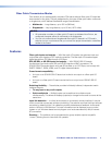
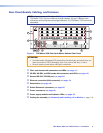
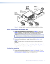
Å Output connector — For all one‑way video, audio, and serial communications
output to a receiver, connect a fiber optic cable to the Output LC connector (see
figure 7, on the previous page).
Connect the far end of this fiber optic cable to the Optical Rx connector on a
FOXBOX Rx receiver or to any other compatible fiber optic device.
NOTES:
• For a FOX 500 receiver, connect this fiber optic cable to the Optical 1 LC
connector.
• Alternatively, for the serial return, (receiver‑to‑transmitter) function,
connect the far end to the Optical RX or Optical 2 connector on a transmitter.
Output LED — See “Fiber optic I/O board LED indications,“ below.
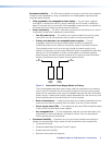
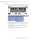
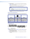
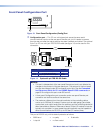
Fiber optic I/O board LED indications
On the fiber optic I/O boards, the input and output LEDs on the transceivers provide useful
indications of the status of the lasers and the reclocking function. See the table below.
OUT
IN
Definition
Output LED
indication
Input LED
indication Definition
Reclocked at 4.25 Gbps On On Reclocked at 4.25 Gbps
Not reclocked, laser off, or
no signal
Off Off Not reclocked or no signal
Non‑4G signal present or
not reclocked
Fast blink Fast blink Non‑4G signal present or
not reclocked
NOTE: If the reclocking feature is set to bypass mode, the output LED is always on.
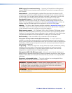
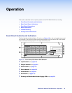
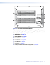
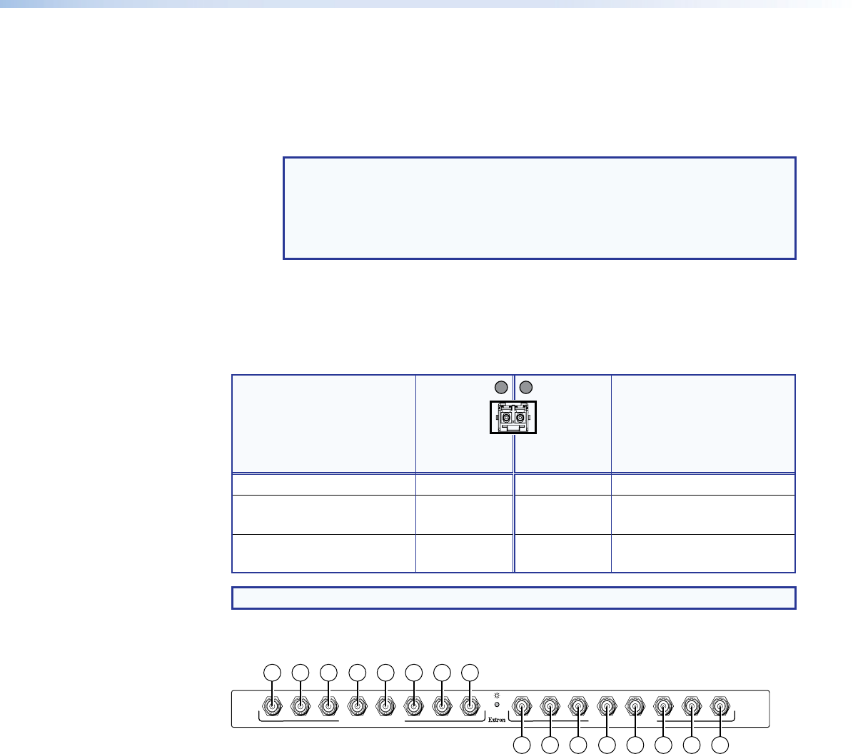
3G/HD/SD-SDI boards
MUTI-RATE SDI INPUTS
H
G
AD
E
F
C
B
MUTI-RATE SDI OUTPUTS
H
G
D
E
F
C
A
B
2b 2b 2b 2b2b 2b 2b 2b
2a 2a 2a 2a2a 2a 2a 2a
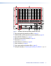
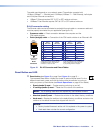
Figure 8. 3G/HD/SD-SDI Board
b BNC board with connectors (see figure 3 on page 8 and figure 4 on page 9) —
Ç Multi-rate SDI Input connectors — Connect HD‑SDI, SDI, or 3G‑SDI video
inputs to these BNC connectors.
É Multi-rate SDI Output connectors — Connect digital displays to these BNC
connectors.
FOX Matrix 3200 and 7200 Switchers • Installation 12