


Click
OK
. The Extron Matrix Switchers Control Program window appears, displaying
the current configuration of the attached matrix (see figure 34 and figure 35 on
the next page). Proceed to step 4.
If you selected
IP
[LAN]
, click
OK
and proceed to step 3.
• If you selected
Emulate
, click
OK
and see Using Emulation Mode on page 89.
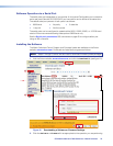
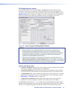
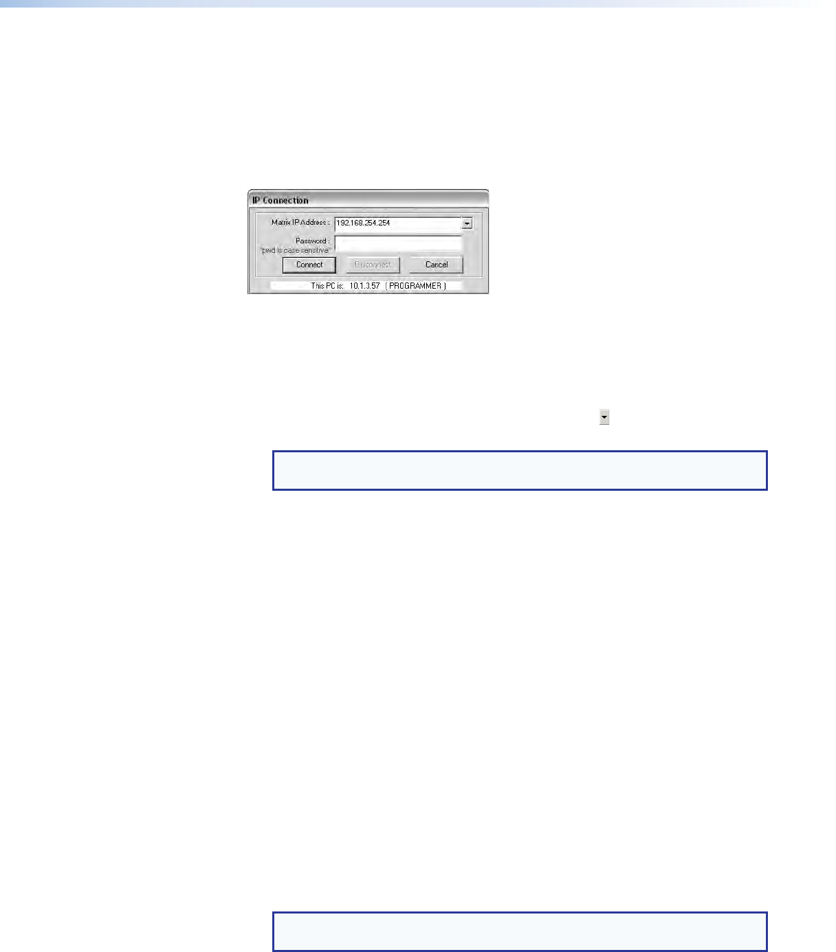
3. If you selected
IP [LAN]
in step 2, the IP Connection dialog box appears
(see figure 33).
Figure 33. Address and Password Entry
a. Examine the Matrix IP Address field in the IP Connection window. The field displays
the last Matrix IP address entered.
If the IP address is correct: Proceed to step 3b.
If the address is not correct: Either click in the
Matrix
IP
Address
field and
enter the IP address or click on the scroll down button ( ) and select from among
the recently used addresses. Proceed to step 3b.
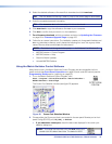
NOTE: If the local system administrators have not changed the value, the
factory‑specified default, 192.168.254.254, is the correct value for this field.
b. If the switcher is password protected, click in the
Password
field and enter the
appropriate administrator or user password.
c. Click
Connect
. The Extron Matrix Switchers Control Program window appears,
displaying the current configuration of the attached matrix (see figure 34 and
figure 35 on the next page). Proceed to step 4.
• If you logged on using the administrator password or if no password was
required, the program connects you to the matrix switcher with all of the
administrator rights and privileges.
• If you logged on using the user password, the program connects you to the
matrix switcher with only user capabilities.
• If an incorrect password was entered, the program beeps and returns to the
password entry display.
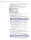
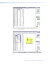
4. Operate the switcher as desired.
• To create a tie, drag an input box to one or more output boxes. To remove a tie,
drag the output box to its tied input box or to the trash can.
• To make the control program easier to use, assign a device icon to each input and
output. Click on a box that represents an input or output, and drag the desired icon
onto the box from the icon palette that appears.
• For quick display of information on a specific input or output device, position the
cursor over that device in the control program window. The program opens a
window that details the connection to that device (see the inset box in figure 35).
TIP: You can print a map of the current configuration by clicking
File
>
Print
Tie Map
.
FOX Matrix 3200 and 7200 Switchers • Matrix Software 74