


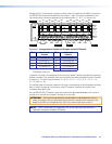
Removing and Installing the Power Supply Module
The two (primary and redundant) power supply modules are identical. Each power supply
module has a 2‑color status LED, visible on the rear panel, that indicates the status of the
power supply outputs. If the LED is lit green, the power supply is operating normally. If the
LED is lit red, the supply has failed and should be replaced at the earliest opportunity.
NOTE: The power supply modules are hot‑swappable. Either power supply can be
removed of installed without powering down the switcher.
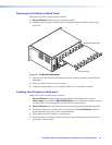
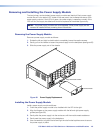
Removing the Power Supply Module
Remove a power supply module as follows:
1. Rotate the left and right knurled knobs to completely loosen the captive screws.
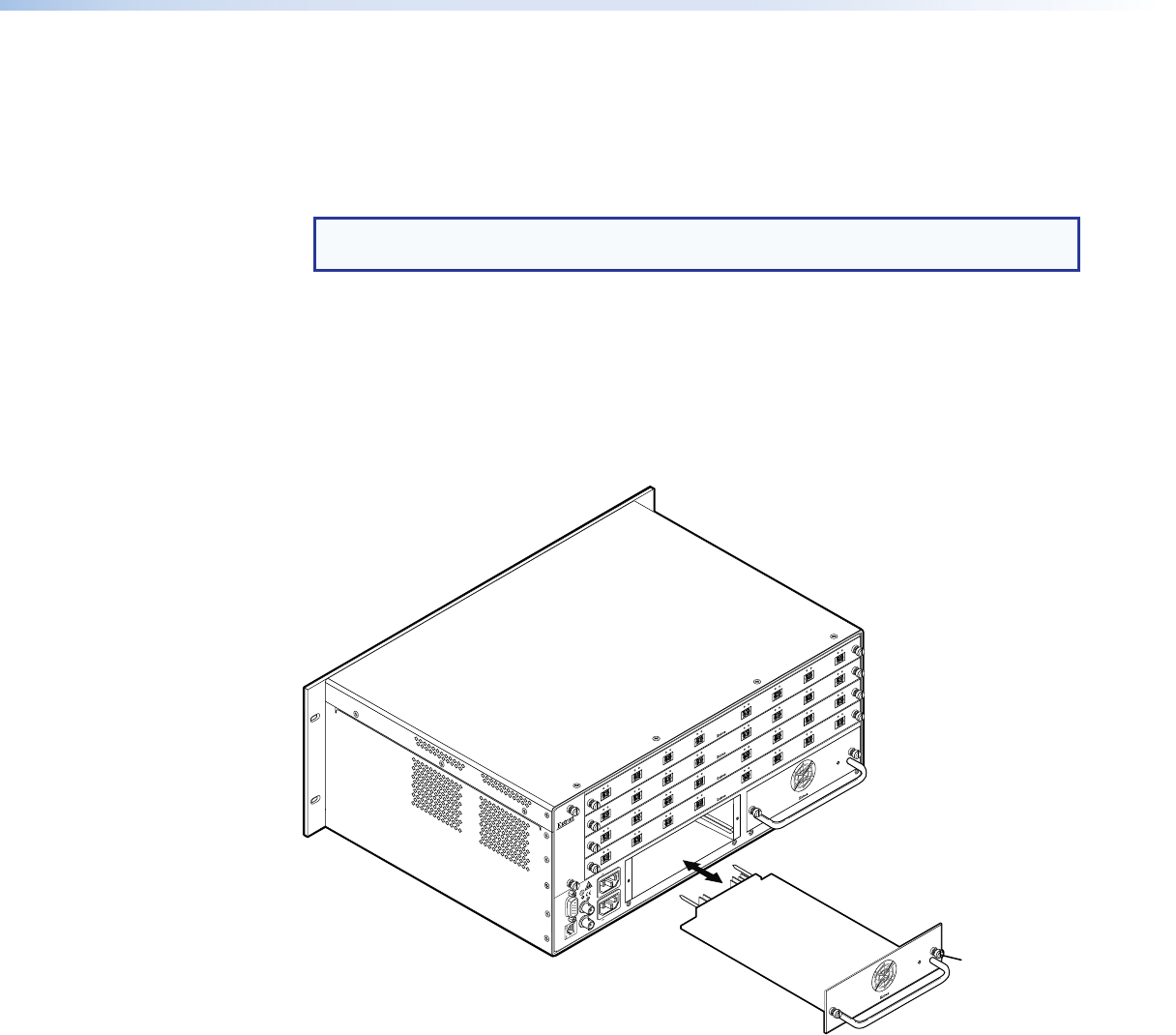
2. Gently pull on the handle to loosen the power supply from the backplane (see figure 66).
3. Slide the power supply out of the chassis.
ANAHEIM, CA
RESET
REMOTE
RS-232/RS-422
LAN
BI-LEVEL
TRI-LEVEL
ACT LINK
100-240V 50/60Hz 1.2A MAX.
100-240V 50/60Hz 1.2A MAX.
REDUNDANT
PRIMARY
DISCONNECT BOTH POWER
CORDS BEFORE SERVICING
SWITCH
REFERENCE
PRIMARY POWER SUPPLY
REDUNDANT POWER SUPPLY
1 - 8
A
B
C
D
E
F
G
H
OUT
IN
OUT
IN
OUT
IN
OUT
IN
OUT
IN
OUT
IN
OUT
IN
OUT
IN
OUT
9 - 16
A
B
C
D
E
F
G
H
OUT
IN
OUT
IN
OUT
IN
OUT
IN
OUT
IN
OUT
IN
OUT
IN
OUT
IN
OUT
17 - 24
A
B
C
D
E
F
G
H
OUT
IN
OUT
IN
OUT
IN
OUT
IN
OUT
IN
OUT
IN
OUT
IN
OUT
IN
OUT
25 - 32
A
B
C
D
E
F
G
H
OUT
IN
OUT
IN
OUT
IN
OUT
IN
OUT
IN
OUT
IN
OUT
IN
OUT
IN
OUT
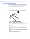
Align with Plastic Guides
Knurled Knobs
Figure 66. Power Supply Replacement
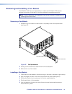
Installing the Power Supply Module
Install a power supply module as follows:
1. Orient the power supply module to be installed with the LED to the right.
2. Align the flanges on the power supply module with the left and right power supply
guides (see figure 66).
3. Gently slide the power supply into the enclosure until the module meets resistance.
4. Gently seat the power supply in the backplane.
5. Use a screwdriver to tighten the left and right knurled knobs/captive screws to secure
the power supply in place.
FOX Matrix 3200 and 7200 Switchers • Maintenance and Modifications 113