


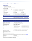
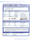
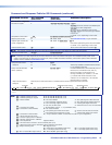
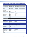

Command and Response Table for SIS Commands (continued)
Command Function SIS Command
(Host to Unit)
Response
(Unit to Host)
Additional description
Information requests
Information request
I
V
X1%
X
X1^
•A
X1%
X
X1^
•S
X1&
1
X1&
2
...
X1&
n
]
V
X1%
X
X1^
shows the number of available inputs
and outputs for this configuration.
A
X1%
X
X1^
has no meaning for this product.
S
X1&
1
X1&
2
...
X1&
n
shows the board type installed
in each slot.
n is either 4 or 9, depending on the model.
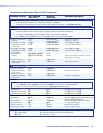
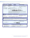
Slot/plane/LC information
0*
X1*
I
X1(
1
X1(
2
X1(
3
X1(
4
X1(
5
X1(
6
X1(
7
X1(
8
]
Request part number
N
68-nnnn-nn
]
See www.extron.com, for part numbers.
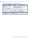
Request part number and
board configuration
*N
68-nnnn-nn.
X1&
1
X1&
2
X1&
3
...
X1&
n
]
Part number (see below) plus I/O boards installed.
n is either 4 or 9, depending on the model.
Read reclocker status
X$
=
X%]
Show current rate status for reclocker
X$
.
NOTE: The switcher automatically detects and reclocks the signal if the rate is 4.25 Gbps only. Other rates are ignored.
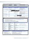
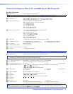
View SFP module status
40*
X2)
S
X2!
•
X2@
•
X2#
•
X2$]
NOTE: There are up to three separate sets of Extron firmware on which the switcher can report: the controller firmware, which is the
overall control firmware; the Ethernet protocol firmware, which handles the Ethernet interface; and the latest optional Extron firmware
update, which is available at www.extron.com.
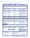
Query firmware version
Q
X2%]
Example:
Q
1.23
]
The factory‑installed controller firmware version
is 1.23 (sample value only).
Query controller firmware
version (verbose)
0Q
X2%
-
X2^
-
X2^]
Provide a detailed status of the Ethernet protocol
firmware, the controller firmware, and any
firmware upgrade. The firmware that is
running is marked by an asterisk (*). A caret
(^) indicates that the firmware has a bad
checksum or an invalid load. ?.?? indicates
that firmware is not loaded.
Response description:
Ethernet protocol firmware version‑controller firmware version‑updated firmware version
]
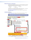
Example:
0q
Ether
net
protocol
firmware
Description
Fiber Matrix firmware version Updated firmware version
* indicates the version running Upload date and time
1.23
-1.00(1.68-FOMX Series -Wed, 20 Feb 2008 00:00:00 GMT)-1.00*(1.06-FOMX Series -Mon, 17 Mar 2007 16:39:21 GMT)
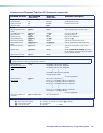
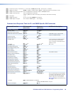
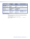
NOTE:
X1%
= Number (quantity) of inputs 8, 16, 24, 32, 40, 48, 56, 64, or 72
X1^
= Number (quantity) of outputs 8, 16, 24, 32, 40, 48, 56, 64, or 72
X1& = Board installed 0 = No board installed 4 = Non‑pathological multimode board
1 = Non‑reclocking multimode board 5 = Non‑pathological singlemode board
2 = Non‑reclocking singlemode board 6 = Pathological singlemode board
3 =
3G, SDI, HD‑SDI board
X = Unknown board or mix of transceivers
X1*
= I/O board slot number 1 – 9 (FOX Matrix 7200) or 1 – 4 ( FOX Matrix 3200)
X1( =
Transceiver module installed
0
= No module installed
1
= Non‑pathological multimode module
3
= 3G‑SDI, HD‑SDI, SD‑SDI module
2
= Non‑pathological singlemode module
4
= Pathological singlemode module
X2)
= Transceiver module number 01 – 72 (or maximum number of transceiver modules for your configuration)
X2!
= Vendor/manufacturer name
X2@
= Transmit output power in milliwatts
X2#
= Receive optical power in milliwatts
X2$
= SFP temperature Degrees Celsius
X2%
= Firmware version number to second decimal place (x.xx)
X2^
= Verbose firmware version‑description‑upload date/time. See above.
X% = Output reclocking rate 00 = Bypass mode
01 = Automatic mode (HDSDI boards only) 03 = 2.125 Gbps (laser boards only)
02 = 1.250 Gbps (laser boards only) 04 = 4.250 Gbps (laser boards only)
X$ = SFP or reclockable output number 00 – 32 or 72 (00 = global [SFP only])
FOX Matrix 3200 and 7200 Switchers • Programming Guide 65