


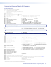
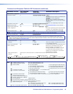
Command and Response Table for SIS Commands (continued)
Command Function SIS Command
(Host to Unit)
Response
(Unit to Host)
Additional description
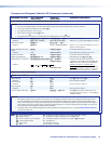
Save, recall, and directly write global presets (continued)
NOTES:
• If a room is not defined (does not exist in the switcher), the matrix switcher responds with the error code E11.
• A room can contain a maximum of 16 outputs (
X@
s).
• An output can belong to only one room.
• The maximum number of rooms (
X*
s) is 10.
• The default name (
X(
) is the room number with four trailing spaces: “Room•#
X*
••••”
Write room outputs
EX*
,
X@
1
,
X@
2
, ...
X@
n
MR
]
Mpr
X*
,
X@
1
,
X@
2
, ...
X@
n
]
See the notes above.
Example:
E
8,3,04,5,6MR
}
Mpr8,03,04,05,06
]
Outputs 3, 4, 5, and 6 are assigned to room 8.
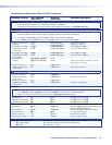
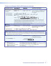
Read room outputs
EX*
MR
}
X(
,
X@
1
,
X@
2
, ...
X@
n
]
Example:
E
3MR
}
Class1,01,02,08,09
]
Outputs 1, 2, 8, and 9 are assigned to room 3,
which is named “Class1”.
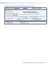
Save current ties as a room
preset
X*
*
X1)
,
Rmm
X*
•Spr
X1)]
Command character is a comma.
Example:
3*9,
Rmm03
•Spr09
]
Save current ties as preset 9 for room 3.
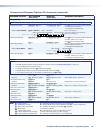
Recall room preset
X*
*
X1)
. Rmm
X*
•Rpr
X1)]
Command character is a period.
Clear room preset ties
E
+
X*
*
X1)
P0*!
]
Rmm
X*
•Spr
X1)]
Clear all ties in room
X*
preset
X1)
.
Directly write a room preset
E
+
X*
*
X1)
P
X!
*
X@
!
X!
*
X@
%
X!
*
X@
! ...
X!
*
X@
&
}
Enter as many ties as are valid for this
configuration. The
! tie command, & tie, and
% tie commands are all valid and equivalent.
Rmm
X*
•Spr
X1)]
Example:
Esc
+7*3P12*7&11*5!4*5%6*6!
Brackets are shown to separate ties for
clarity only. Create preset 3 for room 7, which
ties input 12 to output 7, input 11 to output 5,
input 4 to output 5, and input 6 to output 6.
Rmm07•Spr03
]
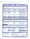
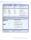
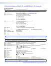
View ties, mutes, and presets
NOTE:
The & read tie command and % read tie command can be used interchangeably.
View output ti
e
X@
!
X!]
Input
X!
is tied to output
X@
.
Example:
1!
05
]
Input 1 is tied to output 5.
View output tie
X@
&
X!]
Example:
15&
27
]
Input 27 is tied to output 15.
View output tie
X@
%
X!]
Example:
7%
02
]
Input 2 is tied to output 7.
View all output mute status
E
VM
}
X#
1
X#
2
X#
3
...
X#
n
Mut
]
Each
X#
response is the mute status of an
output, starting from output 1. n
is the highest‑
numbered output.
NOTES:
• The switcher reports the mute status for all outputs, up to the highest numbered output on the highest numbered slot with an
I/O board installed. The switcher does not recognize gaps in the board installation. For example, if boards are installed in only
slots 1 and 3, leaving slot 2 empty, the switcher returns mute status for 24 sequential outputs. The mute status for the outputs in
slot 2, inputs 9 through 16, can be ones or zeroes (the switcher allows you to mute an output that is not installed, so long as it is
numbered lower than the highest numbered output installed).
• The “Mut” portion of the response appears only when the switcher is in Verbose mode 1 or 3 (see the Set verbose mode SIS
command on page 69).
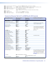
NOTE:
X!
= Input number (for tie) 00 – (maximum number of inputs for your configuration) (00 = untied)
X@
= Output number 01 – (maximum number of outputs for your configuration)
X*
= Room number (for room presets) 01 – 10 maximum (each can have up to 10 presets (
X1)
) assigned)
X1)
= Room preset number 01 – 10 maximum
X(
= Room name 12 characters maximum
X#
= Mute 0 = not muted, 1 = muted
FOX Matrix 3200 and 7200 Switchers • Programming Guide 61