


Removing the I/O Board or Blank Panel
Remove an I/O board or blank panel as follows:
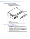
1. For an I/O board, disconnect any connected cables.
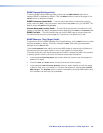
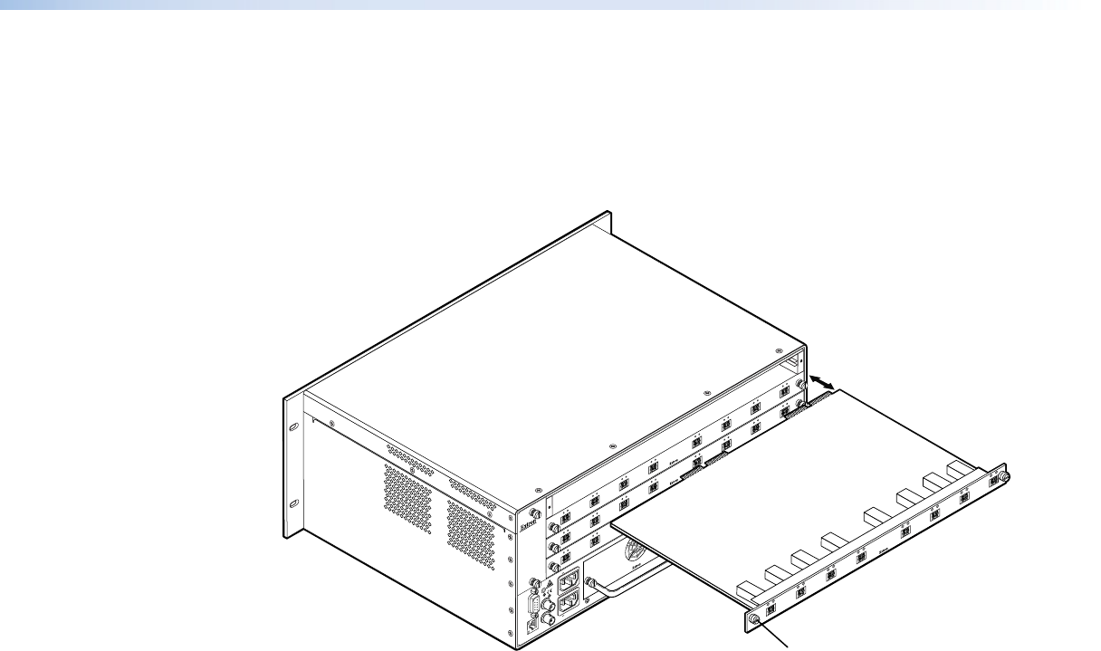
2. Rotate the left and right knurled knobs to completely loosen the captive screws (see
figure 65).
ANAHEIM, CA
RESET
REMOTE
RS-232/RS-422
LAN
BI-LEVEL
TRI-LEVEL
ACT LINK
100-240V 50/60Hz 1.2A MAX.
100-240V 50/60Hz 1.2A MAX.
REDUNDANT
PRIMARY
DISCONNECT BOTH POWER
CORDS BEFORE SERVICING
SWITCH
REFERENCE
PRIMARY POWER SUPPLY
REDUNDANT POWER SUPPLY
1 - 8
9 - 16
A
B
C
D
E
F
G
H
OUT
IN
OUT
IN
OUT
IN
OUT
IN
OUT
IN
OUT
IN
OUT
IN
OUT
IN
OUT
17 - 24
A
B
C
D
E
F
G
H
OUT
IN
OUT
IN
OUT
IN
OUT
IN
OUT
IN
OUT
IN
OUT
IN
OUT
IN
OUT
25 - 32
A
B
C
D
E
F
G
H
OUT
IN
OUT
IN
OUT
IN
OUT
IN
OUT
IN
OUT
IN
OUT
IN
OUT
IN
OUT
Align with Plastic Guides
IN
OUT
IN
A
OUT
IN
B
OUT
IN
C
OUT
IN
D
OUT
IN
E
OUT
IN
F
OUT
IN
G
OUT
IN
H
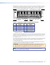
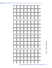
Knurled Knobs
Figure 65. I/O Board Replacement
3. Gently pull on the knurled knobs/captive screws to loosen the board or panel from the
backplane.
4. Slide the board or panel out of the chassis.
5. Place the removed board on an antistatic surface or in an antistatic container.
Installing the I/O board or blank panel
Install an I/O board or blank panel as follows:
1. For an I/O board, orient the board to be installed so that transceiver module A
(fiber board) or input BNC A (SDI/HD-SDI board) is on the left and transceiver module
or output BNC H is on the right as you face the rear of the switcher.
2. For an I/O board, align the board with the left and right chassis guides (see figure 65).
3. Gently slide the board or blank panel into the enclosure. For an I/O board, slide the
board toward the front panel until it meets resistance.
4. Gently seat the board or panel in the backplane.
5. Use a screwdriver to tighten the left and right knurled knobs/captive screws to secure
the board or panel in place.
FOX Matrix 3200 and 7200 Switchers • Maintenance and Modifications 112