


Switch Reference Connections
f Switch Reference connectors for bi-level and tri-level sync (see figure 3 on
page 8 and figure 4 on page 9) — (SDI / HD-SDI inputs and outputs only) Connect
an external sync signal to this BNC connector to genlock the video signal in broadcast
or other sync‑critical applications.
The switcher makes ties to inputs on SDI/HD‑SDI I/O boards during the vertical interval
period of the tied video, resulting in glitch‑free video switching when the input devices
are also using the same sync timing. The FOX Matrix Switcher can use an external
signal to synchronize switching during the vertical interval. Without this external sync
locking feature, switching between inputs could result in brief video or picture rolling
(sync loss) or a brief change in the picture size.
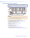
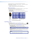
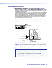
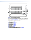
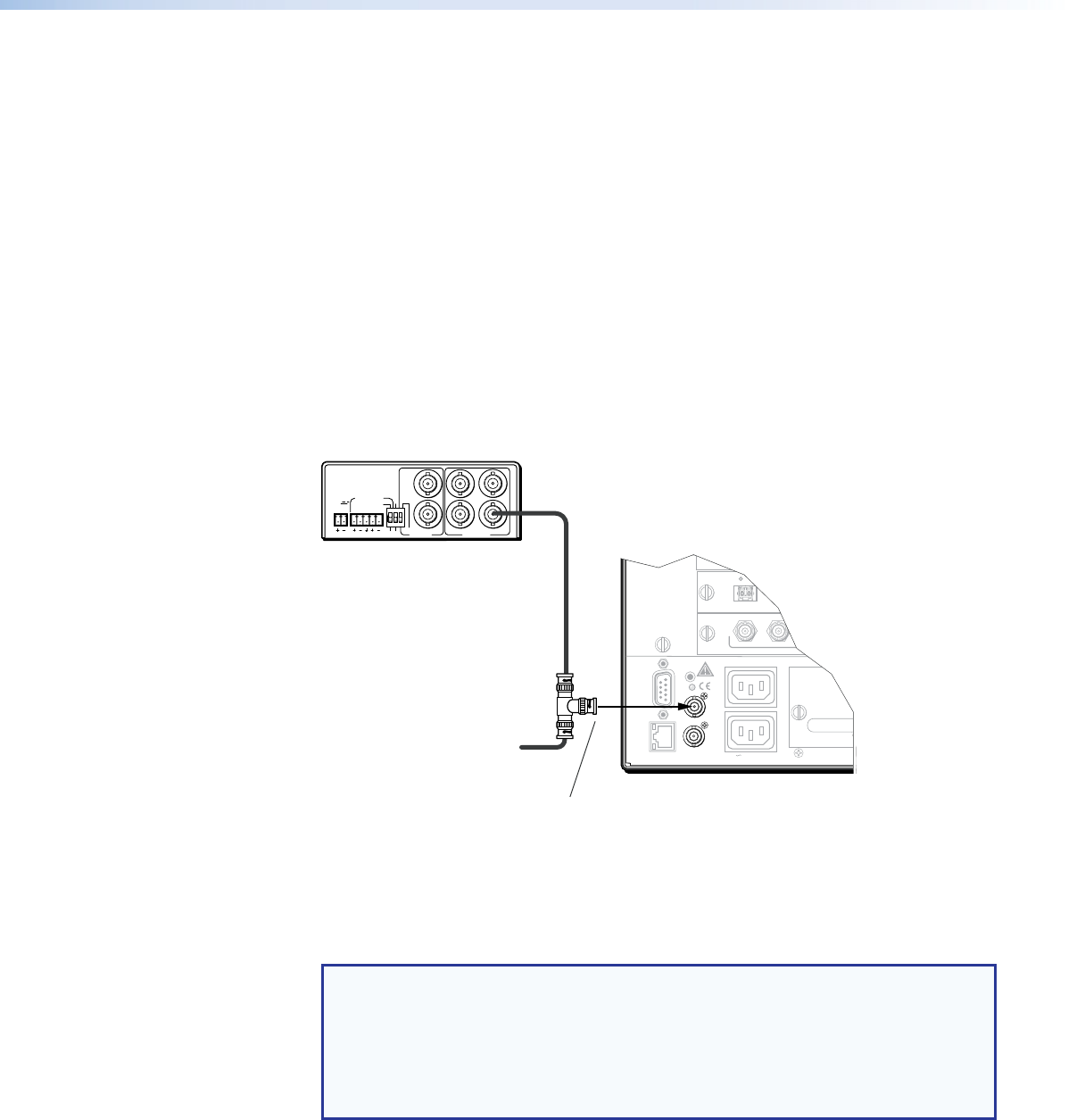
Figure 11 shows a basic external sync configuration. The Bi‑level or Tri‑level sync
connector receives the timing signal. A tee connector attached to the cable allows the
signal to be passed on to another video device, if required. Terminate the tee connector
if desired.
POWER
12V
0.5A MAX
LR
1
4
3
2
1
6
5
PAL
NTSC
BLACKBURST
BLACKBURST/
COLORBAR
-10dBV
+4dBu
1 2 3
ON
1 KHZ AUDIO
BBG 6 A
BLACK BURST/COLOR BAR
/AUDIO GENERATOR
Extron
FOX Matrix 3200
Matrix Switcher
Terminate cable or
connect to another device.
Connect to
FOX Matrix 3200.
Tee-connector
OUT
Extron
BBG 6 A
Black Burst, Color Bars,
and Audio Generator
RESET
REMOTE
RS-232/RS-422
LAN
BI-LEVEL
TRI-LEVEL
ACT LINK
100-240V 50/60Hz 1.2A MAX.
100-240V 50/60Hz 1.2A MAX.
REDUNDANT
PRIMARY
DISCONNECT BOTH POWER
CORDS BEFORE SERVICING
SWITCH
REFERENCE
9
17 - 24
A
OUT
25 - 32
A
B
Figure 11. Simple FOX Matrix Switcher External Sync Connection Example
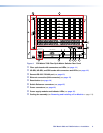
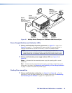
Figure 12 on the next page shows another configuration, in which the timing source
passes through three video cameras and a video scan converter before connecting to
the switcher. This type of video camera is capable of synchronizing with the external
timing source for video editing applications.
NOTE: The Switch Reference connectors are tied into the I/O grouping feature of
the switcher:
• Ties to any input in I/O group 1 use the tri‑level sync reference.
• Ties to any output in I/O group 2 use the bi‑level sync reference.
See I/O grouping on page 33 to assign sync‑critical inputs and outputs to the
appropriate I/O groups.
If no external sync timing source is connected to the switcher, switching occurs
immediately.
FOX Matrix 3200 and 7200 Switchers • Installation 15