


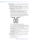
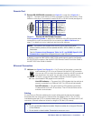
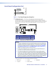
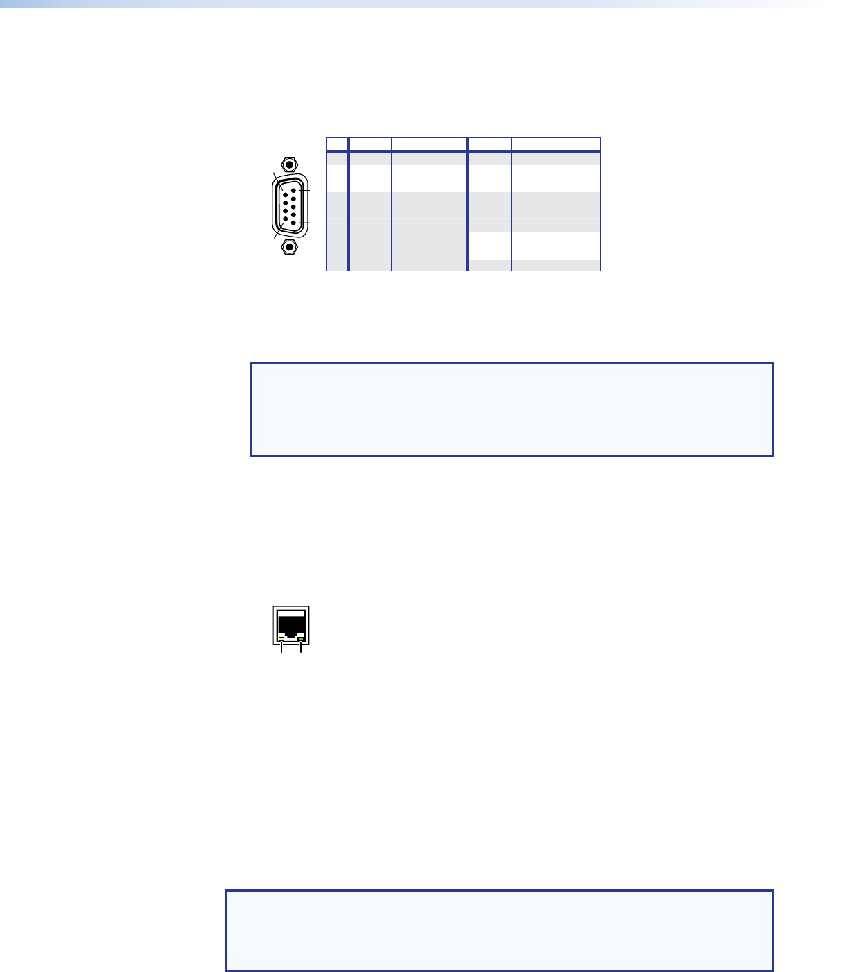
Remote Port
c Remote RS-232/RS-422 connector (see figure 3 on page 8 and figure 4 on
page 9) — Connect a host device, such as a computer or touch panel control, to the
switcher via this 9‑pin D connector for serial RS‑232 or RS‑422 control (see figure 9).
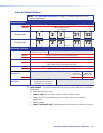
RS-232FunctionPin Function
1
2
3
4
5
6
7
8
9
—
Tx
Rx
—
Gnd
—
—
—
—
Not used
Transmit data
Receive data
Not used
Signal ground
Not used
Not used
Not used
Not used
—
Tx–
Rx–
—
Gnd
—
Rx+
Tx+
—
Not used
Tr
ansmit data (–)
Receive data (–)
Not used
Signal ground
Not used
Receive data (+)
Tr
ansmit data (+)
Not used
RS-422
1
5
6
9
REMOTE
RS-232/RS-422
Figure 9. Remote RS-232/RS-422 Connector
See Programming Guide on page 52 for definitions of the SIS commands (serial
commands to control the switcher via this connector) and Matrix Software on
page 71 for details on how to install and use the control software.
NOTE: The switcher can support either the RS‑232 or the RS‑422 serial
communication protocol, and can operate at 9600, 19200, 38400, or 115200
baud rates.
See the Command and Response Table for IP- and SNMP-Specific SIS
Commands on page 68 to configure this port under SIS control.
If desired, connect an MKP 2000 or MKP 3000 remote control panel to the Remote
RS‑232/RS‑422 connector. See the MKP 2000 Remote Control Panel User Guide or
the MKP 3000 User Guide for details.
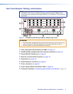
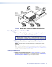
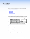
Ethernet Connection
d LAN port (see figure 3 and figure 4) — For IP control of the system, connect the
matrix switcher to a PC or to an Ethernet LAN via this RJ‑45 connector.
You can use a PC to control the networked switcher with SIS commands
from anywhere in the world. You can also control the switcher from a
PC that is running the Extron Matrix Switchers Control Program or has
downloaded HTML pages from the switcher.
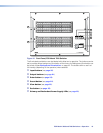
Link LED indicator — The green (link) LED indicates that the switcher is
properly connected to an Ethernet LAN. This LED should light steadily.
Act LED indicator — The yellow (activity) LED indicates transmission
of data packets on the RJ‑45 connector. This LED should flicker as the
switcher communicates.
Cabling
It is vital that your Ethernet cables be the correct cable type and that they be properly
terminated with the correct pinout. Ethernet links use Category (CAT) 3, 5e, or CAT 6,
unshielded twisted pair (UTP) or shielded twisted pair (STP) cables, terminated with RJ‑45
connectors. Ethernet cables are limited to a length of 328 feet (100 meters).
NOTES:
• Do not use standard telephone cables. Telephone cables do not support Ethernet
or Fast Ethernet.
• Do not stretch or bend cables. Transmission errors can occur.
Link
LED
Activity
LED
FOX Matrix 3200 and 7200 Switchers • Installation 13