


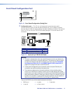
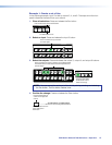
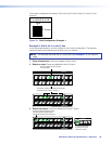
Button Icons
The numbered translucent covers on the input and output buttons can be removed and
replaced to insert labels behind the covers.
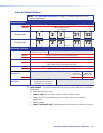
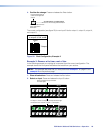
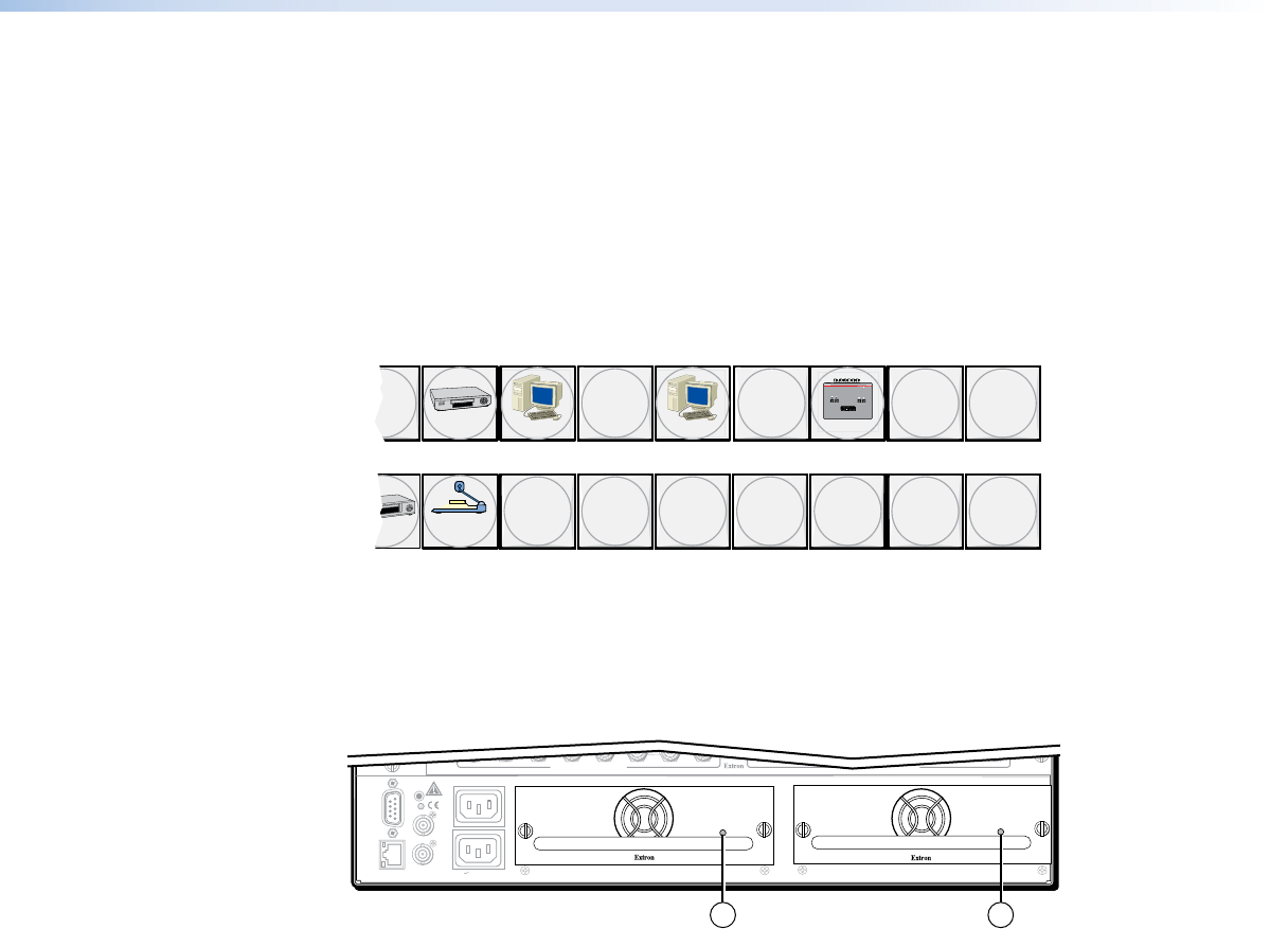
Input and output labels can be created easily with the Extron Button Label Generator
software, which is available on the Extron website (www.extron.com). Each input and
output can be labeled with names, alphanumeric characters, or color bitmaps for easy
and intuitive input and output selection (see figure 17). See the Button Label Generator
Program on page 91 for details on using the labeling software and the Removing and
Installing Button Labels on page 115 for blank labels and a procedure for removing and
replacing the translucent covers.
DVD
VCR
Computer Computer
Document
Camera
VTG 200
10 13 15
3130 32 33 34 35 36
17 18
Figure 17. Sample Button Labels and Icons
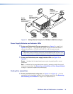
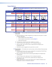
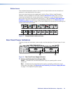
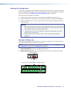
Rear Panel Power Indicators
The two, primary and redundant, power supply modules (see figure 18) each have a 2‑color
LED.
RESET
REMOTE
RS-232/RS-422
LAN
BI-LEVEL
TRI-LEVEL
ACT LINK
100-240V 50/60Hz 1.2A MAX.
100-240V 50/60Hz 1.2A MAX.
REDUNDANT
PRIMARY
DISCONNECT BOTH POWER
CORDS BEFORE SERVICING
SWITCH
REFERENCE
PRIMARY POWER SUPPLY
REDUNDANT POWER SUPPLY
2
MUTI-RATE SDI INPUTS MUTI-RATE SDI OUTPUTS
1 1
Figure 18. Rear Panel Power Supply Indicators
a Primary and Redundant Power Supply LEDs —
Green — Indicates that the associated power supply is operating within normal
tolerances.
Red — Indicates that the associated power supply is operating outside the normal
tolerances or has failed. See Removing and Installing the Power Supply Module
on page 113 to replace the power supply.
FOX Matrix 3200 and 7200 Switchers • Operation 24