


User's ManualD-4
INTERFACE INFORMATION
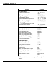
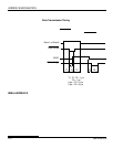
Data Transmission Timing
The Centronics interface of this printer guarantees the received data
when the Data and Data Strobe signals from the computer have the
following timing with respect to the Busy and Acknowledge signals
from the printer.
➤
➤
➤
➤
➤
➤
➤
➤
➤
➤
➤
➤
T5 T6
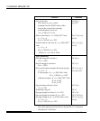
T1, T2, T3 > 1 µs
T4 < 1 µs
0 µs < T5 < 3 µs
2 µs < T6 < 6 µs
T1
Data 1 to Data 8
Data Strobe
BUSY
Acknowledge
T2 T3
T4
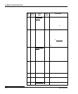
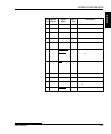
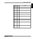
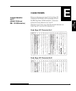
SERIAL INTERFACE
RS-232C is the standard serial interface for data terminal equipment.
The cable connector at the printer side should be a D-subminiature
Cannon or Cinch DB-25P male connector or equivalent that conforms
to EIA standards.
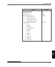
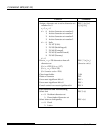
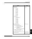
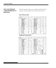
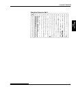
The table that follows shows the pin assignments commonly used by
most computers. In the table:
•“Input” denotes a signal from the computer to the printer.
•“Output” denotes a signal from the printer to the computer.
•The signal level for mark state (logical 1) is -3 V or lower; for
space state (logical 0), it is +3 V or higher.