


Logic Editors
LD Editor
66 CIMPLICITY Logic Developer - PLC Version 4.00 GFK-1918D
5
LD EDITOR
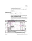
The Ladder Diagram (LD) editor is used to create programs with the Ladder
Diagram programming language. LD logic graphically represents the programmed
actions performed by a PLC as it executes.
The LD editor is cell-based with rungs constructed of horizontal sequences of
instructions that are wired together. A given instruction and its operands can
occupy one or more cells.
You can work with the LD editor while offline to edit a disk copy of a project, or
while online to monitor the execution of the logic while you fine tune the project
by making word-for-word changes (see page 73).
You can customize the appearance and behavior of the LD editor.
An LD block is a named section of LD Logic that is compiled and downloaded to
the PLC represented by the associated target. The following table describes the
number of blocks supported by each CPU type for a given target.
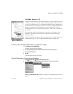
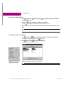
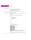
To customize the LD editor
1. In the Options tab of the Navigator, expand the Editors folder and then the Ladder folder.
2. Right-click a page (Confirmations, Editing, Font and Colors, or View), and choose Properties.
The configurable settings appear as properties in the Inspector.
3. In the Inspector, adjust settings as required.
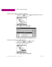
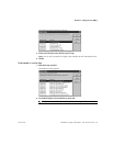
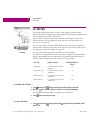
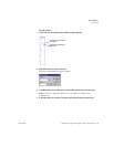
To create an LD block
1. In the Project tab of the Navigator, right-click the Program Blocks folder point to New, and then
choose LD Block.
CPU Type Number of Blocks Maximum Number of
Blocks
VersaMax
64 subroutine blocks plus one
_MAIN block
65
Series 90™-30
64 subroutine blocks plus one
_MAIN block
65
Series 90™-70
255 subroutine blocks plus one
_MAIN block
256
PACSystems™
511 subroutine blocks plus one
_MAIN block
512
Navigator: Project tab
An LD Block