


Component locations
This section provides illustrations of the system board, Diagnostic LED panel,
memory board, and Advanced System Management Interconnect board component
locations.
System board component locations
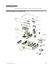
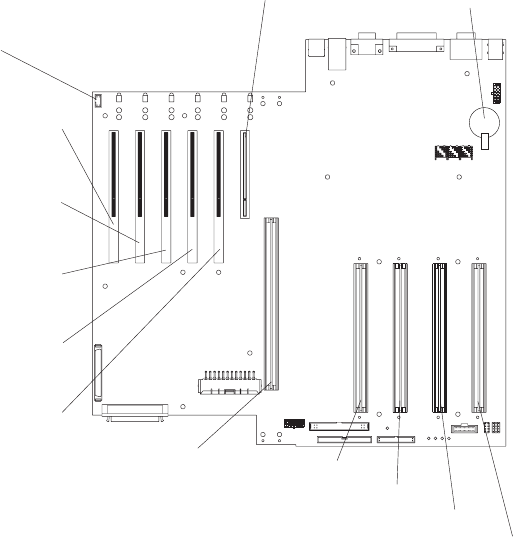
The following illustrations detail certain locations on the system board.
Note: The illustrations in this document might differ slightly from your hardware.
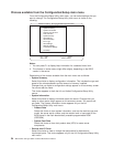
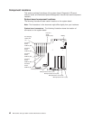
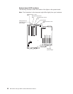
System board connectors: The following illustration shows the location of
connectors on the system board.
PCI slot 1
32-bit
33 MHz (J50)
PCI slot 2
64-bit
66 MHz (J51)
PCI slot 3
64-bit
66 MHz (J52)
PCI slot 4
64-bit
66 MHz (J53)
PCI slot 5
64-bit
33 MHz (J54)
PCI slot 6
64-bit
33 MHz (J55)
Microprocessor slot 1 (J34)
Microprocessor slot 2 (J35)
Microprocessor slot 3 (J36)
Microprocessor slot 4 (J37)
Memory board (J40)
Battery
PCI hot-plug
switch card
(J1)
42 IBM xSeries 350 Type 8682: Hardware Maintenance Manual