


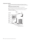
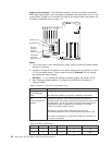
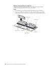
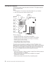
Memory board component locations
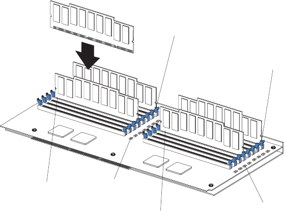
The following illustration shows the location of the dual inline memory module
(DIMM) connectors and error LEDs on the memory board.
Notes:
1. The illustrations in this document might differ slightly from your hardware.
2. Some of the DIMM error LEDs are not visible in this illustration. The memory
board contains 16 error LEDs; that is, one error LED for each DIMM connector.
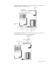
Memory slot 1
Memory slot 5
Memory slot 9
Memory slot 13
Error LEDs
Error LEDs
48 IBM xSeries 350 Type 8682: Hardware Maintenance Manual