


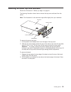
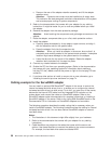
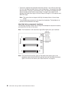

v The server supports three standard and three optional 1-inch (26 mm) slim-high,
3.5-inch, hot-swap hard disk drives in the hot-swap bays. The standard hot-swap
bays are bays 1 through 3 (from bottom to top). The optional hot-swap bays are
bays 4 through 6 (from bottom to top). Bays 1 through 3 are located in the
standard hard disk drive cage, to the left of bays 4 through 6 in the optional hard
disk drive cage.
Note: The server does not support half-high hot-swap drives or internal tape
drives.
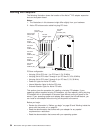
v The hot-swap bays connect to a hot-swap drive backplane. The backplane is a
printed circuit board behind the bays.
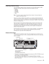
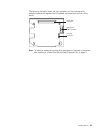
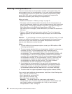
Hard disk drive component locations
The following illustration shows the hot-swap-drive backplane component locations,
as viewed from the front of the server.
Note: The illustrations in this document might differ slightly from your hardware.
Hard disk
drive activity
light (green)
Hard disk
drive status
light (amber)
SCSI hot-swap
hard disk drive
connector
Note: The hard-disk drive activity light and hard-disk drive status light on the
backplane match the hard-disk drive activity light and hard-disk drive status
light on the front of the server (see “Start the server” on page 8).
60 IBM xSeries 350 Type 8682: Hardware Maintenance Manual