


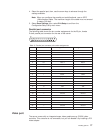
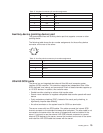

Table 15. Keyboard connector pin-number assignments
Pin I/O Signal
1 I/O Data
2 N/A Reserved
3 N/A Ground
4 N/A +5 V dc
5 I/O Keyboard clock
6 N/A Reserved
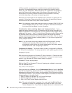
Auxiliary-device (pointing device) port
The system board has one auxiliary-device port that supports a mouse or other
pointing device.
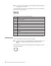
The following table shows the pin-number assignments for the auxiliary-device
connector on the rear of the server.
6
4
2
1
3
5
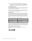
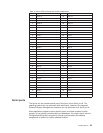
Table 16. Auxiliary-device connector pin-number assignments
Pin Signal
1 Data
2 Not connected
3 Ground
4 +5Vdc
5 Clock
6 Not connected
Ultra160 SCSI ports
The server has an integrated dual-channel Ultra160 small computer system
interface (SCSI) controller. This controller supports two independent Ultra 160/m
SCSI channels: one internal and one external. Each of these channels supports up
to 15 SCSI devices. In addition, this controller uses:
v Double-transition clocking to achieve high transfer rates
v Domain name validation to negotiate compatible data transfer speeds with each
device
v Cyclic-redundancy checking (CRC), instead of the usual parity checking, to
significantly improve data reliability
v An active terminator on the system board for SCSI bus termination
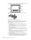
The server comes with two SCSI cables. One cable connects the internal SCSI
channel connector to the standard hot-swap-drive backplane. The other cable is not
connected to the server when the server is shipped and must be installed in the
server. If you want to use the external LVD SCSI channel connector to connect
external SCSI devices to the server, remove the knockout on the rear of the server
and install the LVD SCSI cable that comes with the server.
Installing options 79