ProSecure Web/Email Security Threat Management (STM) Appliance Reference Manual
1-12 Introduction
v1.0, September 2009
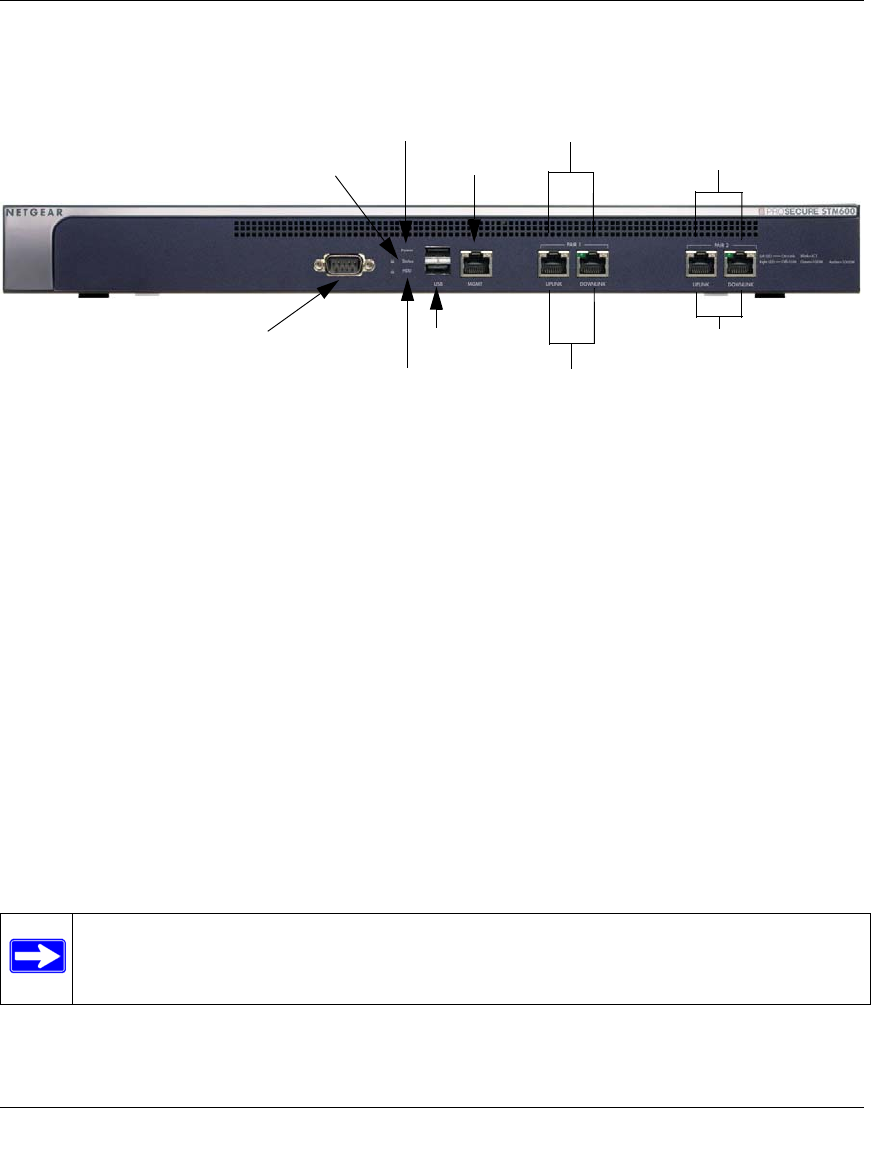
Front Panel STM600
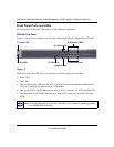
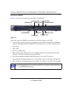
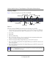
Figure 1-4 shows the front panel ports and LEDs of the STM600.
From left to right, the STM600’s front panel shows the following ports and LEDs:
1. Console port. Port for connecting to an optional console terminal. The ports has a DB9 male
connector. The default baud rate is 9600 K. The pinouts are: (2) Tx, (3) Rx, (5) and (7) Gnd.
2. Power LED.
3. Status LED.
4. Hard drive (HDD) LED.
5. One non-functioning USB port: this port is included for future management enhancements.
The port is currently not operable on any STM model.
6. Dedicated management (Mgmt) Gigabit Ethernet port with an RJ-45 connector.
7. Pair 1 uplink (WAN) and downlink (LAN) Gigabit Ethernet ports with RJ-45 connectors, left
LEDs, and right LEDs.
8. Pair 2 uplink (WAN) and downlink (LAN) Gigabit Ethernet ports with RJ-45 connectors, left
LEDs, and right LEDs.
Figure 1-4
Note: All Gigabit Ethernet ports provide switched N-way, automatic speed-negotiating,
auto MDI/MDIX technology.
3) Status LED
4) HDD LED
5) USB Port
2) Power LED
1) Console Port
6) Mgmt Port
7) Pair 1 LEDs
8) Pair 2 LEDs
7) Pair 1 Ports
8) Pair 2 Ports


