


WLAN Application Gateway 2246 installation 91
the correct minimum spacing between units. When mounting
multiple units, stack the units in the rack as closely as possible.
--End--
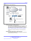
LAN connection
Use an RJ-45 cable to connect the NETWORK port on the WLAN IP
Telephony Manager 2245 to the connecting port on the Ethernet switch.
Power connection
Follow the steps in Procedure 4 “Connecting the power” (page 91) to
connect the power to the WLAN IP Telephony Manager 2245.
Procedure 4
Connecting the power
Step Action
1 Connect the power plug from the AC adapter to the jack labeled
PWR on the WLAN IP Telephony Manager 2245.
WARNING
Use only the provided Class II AC adapter with output
24V DC, 1A.
2 Plug the AC adapter into a 110V AC outlet to supply power to
the WLAN IP Telephony Manager 2245.
The system cycles through diagnostic testing and the LEDs blink
for approximately one minute.
3 When the system is ready for use, verify the following:
a ERROR LED is off.
b Status 1 is blinking.
--End--
WLAN Application Gateway 2246 installation
For information about installing the optional WLAN Application Gateway
2246, see “WLAN Application Gateway 2246” (page 141).
Nortel Communication Server 1000
WLAN IP Telephony Installation and Commissioning
NN43001-504 03.04 Standard
23 September 2008
Copyright © 2004–2008 Nortel Networks
.