C1553M-B (4/05) 243
d. Add clients, custom windows, and canvases: If you have not already done so, add each client that will access Server A’s video.
If signals from Server A are going to be viewed in a custom window, add the window and configure the appropriate type of canvas for
the window. Refer to Clients, Custom Windows, and Canvases for instructions.
e. Save configuration: Exit configuration mode and save Server B’s configuration. Refer to Starting and Stopping the Server for
instructions.
f. Run Server B: If it is not already running, put Server B in run mode. Refer to Starting and Stopping the Server for instructions.
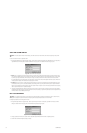
TEST A SERVER TIE
1. Log in to the VMX300(-E) client, connecting to both Server A and Server B, with Server B as your home server. Refer to Configuring Servers
in the VMX300(-E) Client Operation Manual for instructions on selecting the servers to connect to.
2. Drag the Server A source device to the destination configured on Server B. Make sure you drag the source to the correct destination. For
example, if you are testing an analog server tie, you must drag the source device connected to the server tie in Server A’s connections
(Cam1 in Configure a Server Tie step 1.c) to the destination device connected to the server tie in Server B’s connections (Monitor in
Configure a Server Tie, step 2.c). The signal from the source device loads and appears in the destination device.
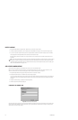
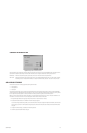
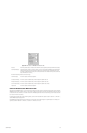
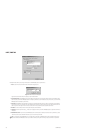
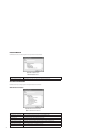
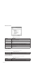
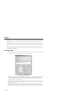
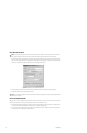
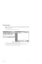
ADD A NEW SERVER TIE
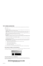
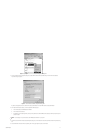
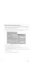
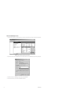
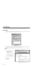
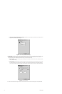
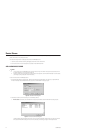
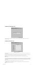
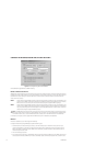
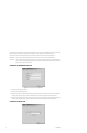
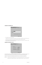
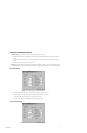
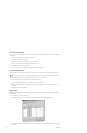
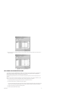
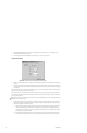
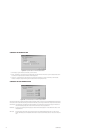
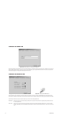
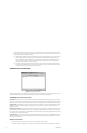
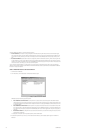
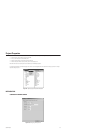
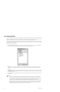
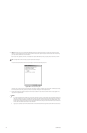
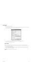
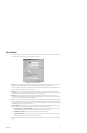
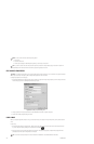
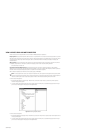
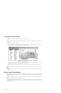
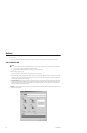
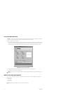
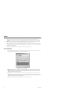
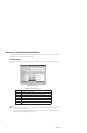
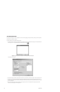
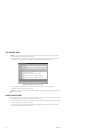
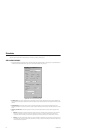
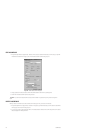
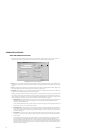
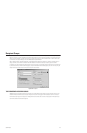
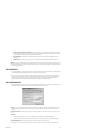
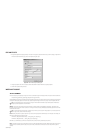
1. Navigate the Object Browser to [project name] > Server Ties. Double-click <Add New Server Tie> in the right pane, or right-click Server Ties
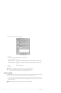
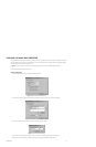
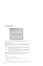
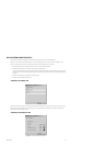
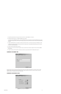
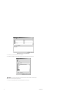
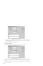
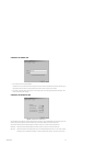
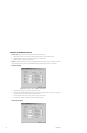
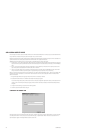
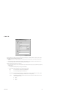
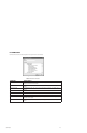
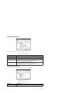
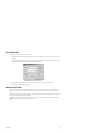
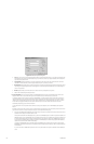
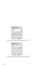
in the left pane and select Add New from the pop-up menu. The Add New Server Tie dialog box opens.
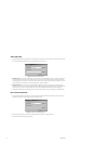
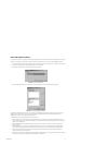
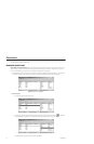
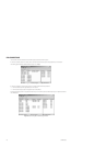
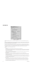
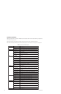
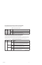
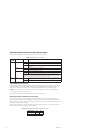
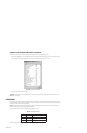
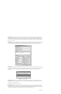
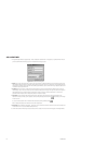
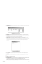
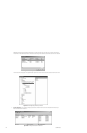
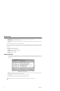
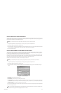
Figure 269. Add New Server Tie Dialog Box
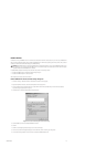
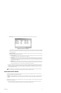
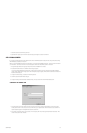
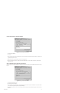
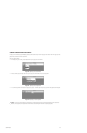
2. Name: Type in a unique, descriptive name for the server tie you want to create. Server tie names are at most 50 characters long and can
include any letter, digit or special character, with the exception of single and double quotation marks. Server tie names are not case
sensitive.
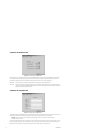
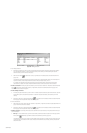
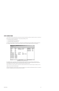
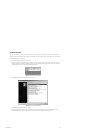
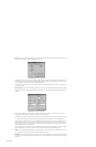
3. Remote server name: Type in the name of the server you want to share signals with, or click Browse to open a list of servers to select
from.
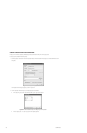
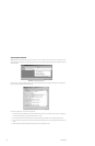
4. Behavior:
a. To share IP signals, select Dynamic (IP). A list of available types of IP signals appears in the Signal Compatibility box.
b. To share analog signals, select Fixed (Analog). A list of available types of analog signals appears in the Signal Compatibility box.
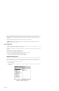
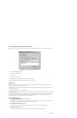
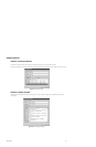
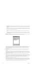
5. Signal compatibility: Select the type of signal you want this server tie to share from the drop-down list.
6. Click OK. The server tie is created and the Add New Server Tie dialog box closes. The new server tie appears in the Object Browser.
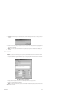
NOTE: If you add a new camera to Server A, you can use an existing server tie to access video from the camera, provided the server tie is
for the correct signal type. To make the new camera available to Server B, you must synchronize Server B’s configuration. Synchronization is
performed automatically when you log in to configuration mode on Server B, or you can synchronize explicitly by editing the remote server
driver and clicking Synchronize.