


Controls and Connectors
11-32 Monitor Installation and Patient Safety
Monitor Installation
and Patient Safety
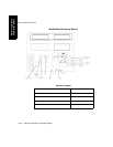
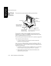
M1167/77A
System
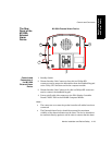
The display module (M1095A) cannot be attached to the computer
module (M1046B). It is designed for mounting on a horizontal or vertical
rail such as an I.V. pole. For further details, please refer to the CMS
Service Guide, chapter 2; Installing CMS.
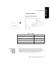
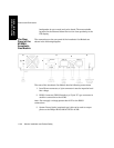
The computer module can be attached to the top or bottom of the
Anesthetic Gas Module by a locking device. This is a lever which is
operated from the rear of the monitor, and is attached to the bottom of
both pieces of equipment.
To assemble the computer module and Anesthetic Gas Module:
• Ensure that the locking lever is in the far right position.
• Place the Anesthetic Gas Module onto the computer module,
ensuring that its four feet are in their correct grooves.
• Push the locking lever from right to far left. The equipment is now
secure.
To dismantle the computer module and Anesthetic Gas Module:
• Push the locking lever from left to far right.
• Lift the Anesthetic Gas Module off the computer module.
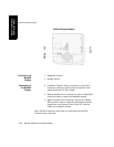
M1165/66/
75/76A
System
The display module (M1094B/92A) can be attached to the computer
module (M1046A) by a locking device. This is a lever which is operated
from the rear of the monitor, and is attached to the bottom of the display
module.
To assemble the computer module and display module:
• Ensure that the locking lever is in the far right position.
• Place the display module onto the computer module, ensuring that
its four feet are in their correct grooves.
• Push the locking lever from right to far left. The equipment is now
secure.
To dismantle the computer module and display module:
• Push the locking lever from left to far right.
• Lift the display module off the computer module.