


6 – Removal/Replacement
CPU Module
59043-06 A 6-5
0
6.2.2
Installing the CPU Module
To install the CPU module, do the following:
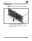
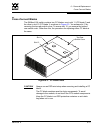
1. Slide the CPU module into the slot guide until it makes contact with the
backplane connector. Rotate the blade latch upward to lock the CPU module
in place. Fasten the screws.
2. Reconnect the Ethernet and serial cable to the CPU module.
3. Power up the switch. Reconnect both power cords to the power supply
modules.
4. Observe the Heartbeat LED. It should blink once per second. If the
Heartbeat LED is showing a different blink pattern, refer to ”Heartbeat LED
Blink Patterns” on page 5-2 for diagnostic procedures or contact your
authorized maintenance provider.
5. Verify the POST results. Open a Telnet session with the default IP address
(10.0.0.1), and enter the Show Slot command to display the diagnostic
status for the CPU module. Refer to the ”Show Command” on page B-62.
You could also display the diagnostic status using the Switch tab or Blade
Info tab of the SANsurfer Switch Manager faceplate display. Refer to the
SANbox2-64 Switch Management User’s Guide.
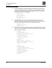
6. Compare firmware versions. Open a Telnet session and enter the Show
Version command to determine the firmware version.
If the firmware versions on the two CPU modules are the same,
proceed to step 9 to restore the switch configuration.
If the firmware versions are different, proceed to step 7 to install
firmware.
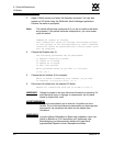
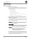
7. Install firmware. Acquire the firmware image file from your own storage or
you can download firmware from the QLogic web site.
Note: A “Failed” status could indicate a faulty blade or module. Enter
the Show POST Log command for more information or contact
your authorized maintenance provider.