2 – General Description
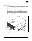
Chassis Hardware
59043-06 A 2-3
0
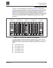
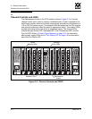
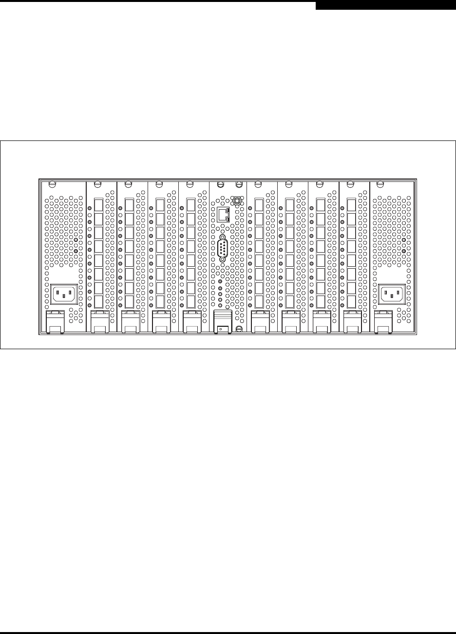
There are 11 slots numbered #0–#10 as shown in Figure 2-2. Power supply
modules occupy slots #0 and #10. The CPU module occupies slot #5. I/O blades
occupy slots #1–#4 and #6–#9. The Fibre Channel ports on the I/O blades are
numbered 0–63 from top to bottom according to slot number as shown in
Figure 2-2. For example, the ports 0–7 are always associated with the I/O blade in
slot #1; ports 8–15 are always associated with slot #2, and so on. For example, if
there were no I/O blade in slot #1, I/O blade #2 would retain the 8–15 port
numbering.
Figure 2-2. Slot and Fibre Channel Port Numbering
The base SANbox2-64 switch comes with I/O blades in slots 1 and 9. You can
expand the switch to 24, 32, 40, 48, 56, or 64 ports by installing 1, 2, 3, 4, 5, or 6
additional I/O blades. Install additional I/O blades in open slots in the following
order:
3rd I/O blade in slot 2
4th I/O blade in slot 8
5th I/O blade in slot 3
6th I/O blade in slot 7
7th I/O blade in slot 4
8th I/O blade in slot 6
1
0
2
3
4
5
6
7
9
8
10
11
12
13
14
15
25
24
26
27
28
29
30
31
17
16
18
19
20
21
22
23
33
32
34
35
36
37
38
39
41
40
42
43
44
45
46
47
49
48
50
51
52
53
54
55
57
56
58
59
60
61
62
63
Slot #0 Slots #1–#4 Slot #5 Slots #6–#9 Slot #10


