


2 – General Description
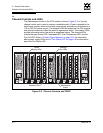
Fibre Channel Ports
59043-06 A 2-7
0
2.2.2.3
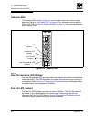
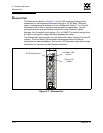
Heartbeat LED (Amber)
The Heartbeat LED indicates the status of the internal switch processor and the
results of the Power On Self Test (POST). Following a normal power-up, the
Heartbeat LED blinks about once per second to indicate that the switch passed
the POST and that the internal switch processor is running. In maintenance mode,
the Heartbeat LED illuminates continuously. Refer to “Heartbeat LED Blink
Patterns” on page 5-2 for more information about Heartbeat LED blink patterns.
2.2.2.4
Input Power LED (Green)
The Input Power LED indicates the voltage status at the switch logic circuitry.
During normal operation, this LED illuminates to indicate that the switch logic
circuitry is receiving the proper DC voltages.
2.3
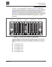
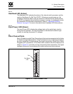
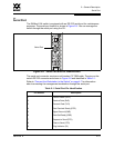
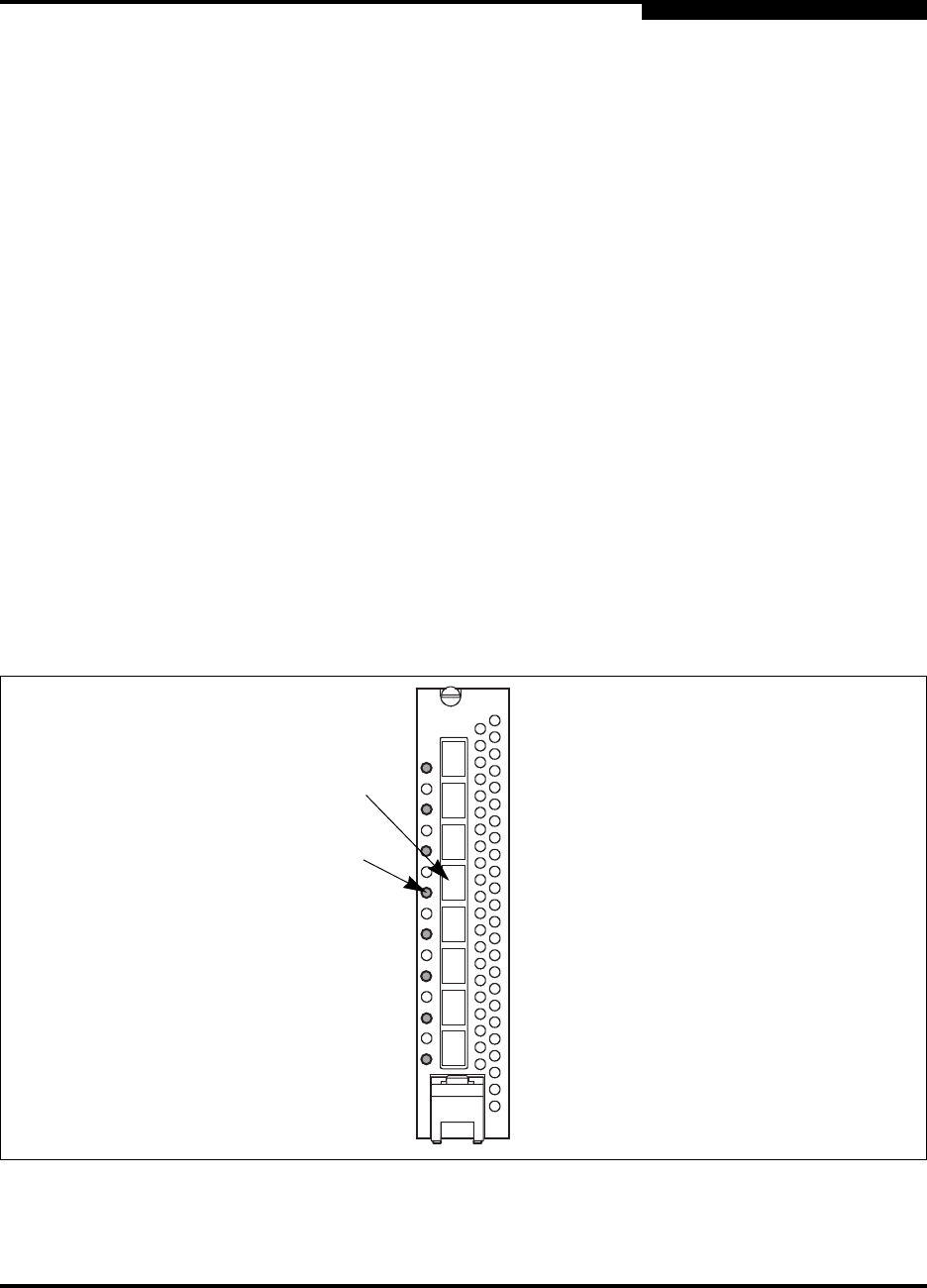
Fibre Channel Ports
Each I/O blade has eight Fibre Channel ports that are interconnected with all other
I/O blades through the backplane. Fibre Channel ports are numbered according to
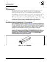
the slot in which the I/O blade resides. Each port is served by a Small Form-Factor
Pluggable (SFP) transceiver. A Port Status LED, located to the left of each port as
shown in Figure 2-5, provides port login and activity status information. Port types
configure the ports to communicate with public devices and other switches.
Figure 2-5. Fibre Channel Ports
Port
Port Status
LED