


2 – General Description
Power Supply Modules
2-12 59043-06 A
0
2.6
Power Supply Modules
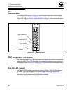
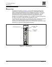
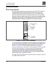
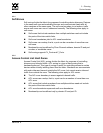
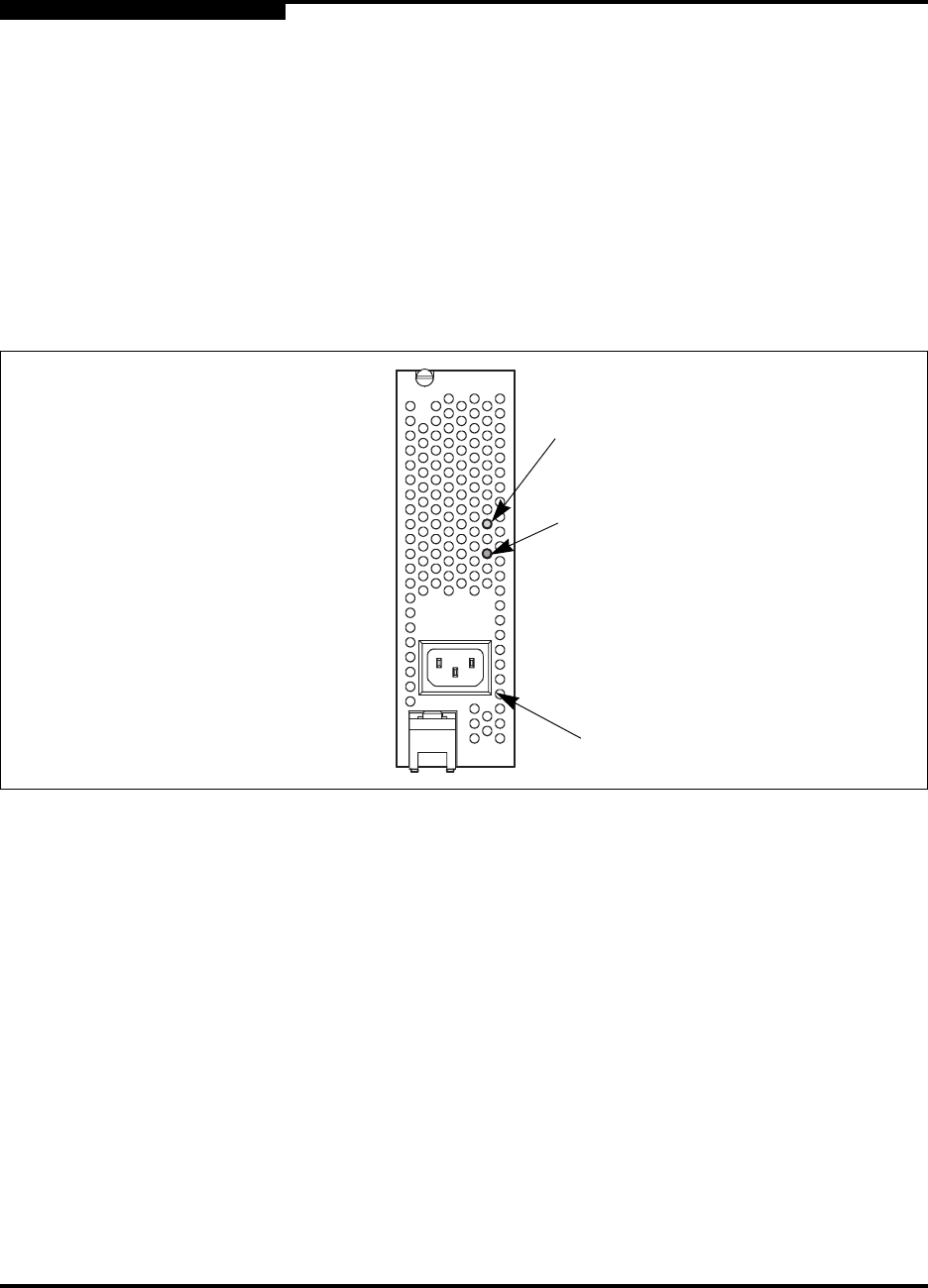
The power supply modules convert standard 110 or 230 VAC to DC voltages for
the various switch circuits. Each power supply module has an AC power
receptacle and two status LEDs as shown in Figure 2-9. Each power supply
module is capable of providing all of the switch’s power needs. During normal
operation, each power supply provides half of the demand. If one power supply
goes offline, the second power supply steps up and provides the difference. After
connecting a power supply to an AC voltage source, the power supply is
energized and the DC voltages are delivered to the switch logic circuitry.
Figure 2-9. Power Supply Components
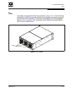
The power supplies are hot pluggable and interchangeable. Hot pluggable means
that you can remove and replace one of the two operating power supplies while
the switch is in operation without disrupting service. Refer to “Power Supply
Modules” on page 6-16 for information about replacing a power supply.
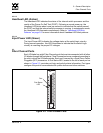
Each power supply has two status LEDs: a Power Supply Fault LED (amber) and
an Output Power LED (green). The Power Supply Fault LED illuminates to
indicate a power supply fault. Possible power supply faults include high
temperature, high or low input voltage, high or low output voltage, and high
current. Refer to Section 5 Diagnostics/Troubleshooting for information about
troubleshooting power supply fault conditions.
The Output Power LED illuminates to indicate that the power supply is producing
DC voltage at the proper levels.
AC Power
Receptacle
Output Power LED
(Green)
Power Supply
Fault LED
(Amber)