


6 – Removal/Replacement
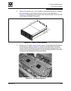
Power Supply Modules
59043-06 A 6-17
0
1. Confirm that the Heartbeat LED is showing the normal 1 blink per second.
This allows the switch to correctly report power supply status.
2. Disconnect the power cord from the power supply module.
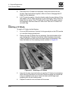
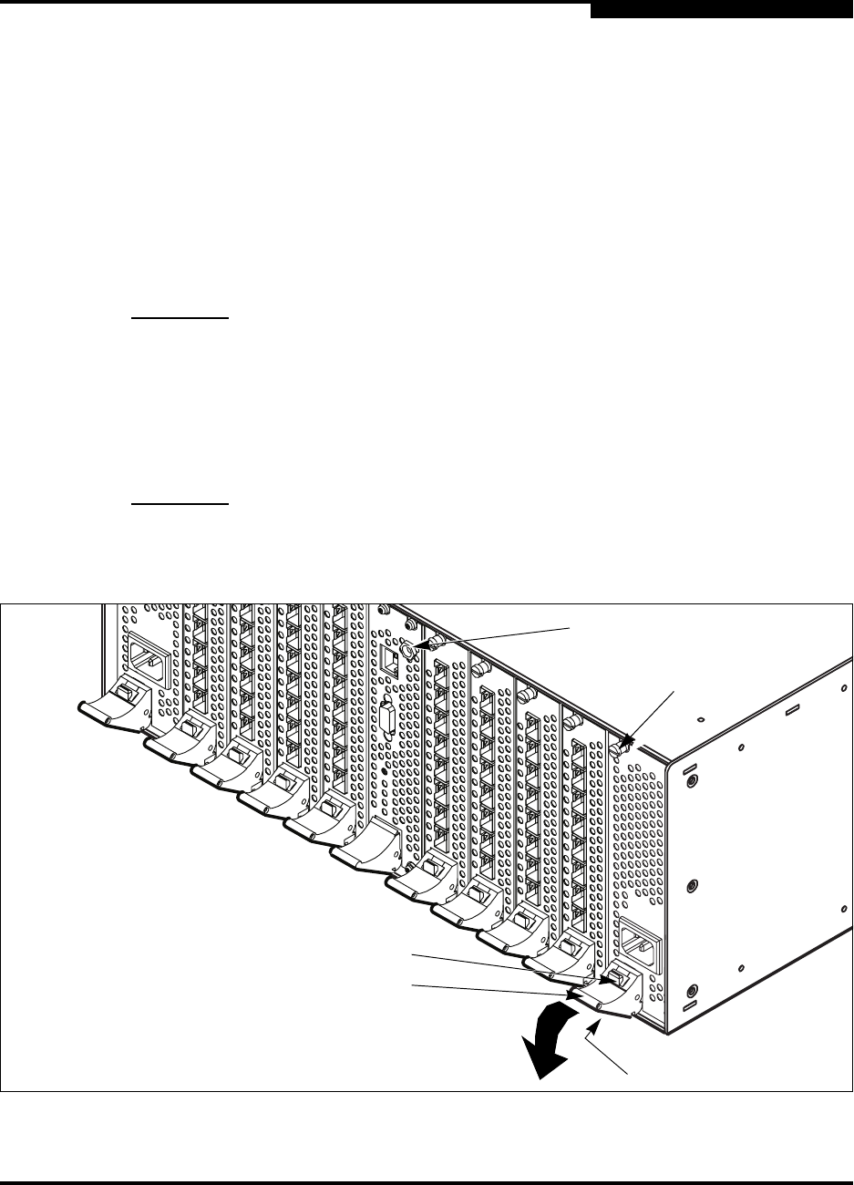
3. Connect an ESD wrist strap to the ground jack on the CPU module shown in
Figure 6-7 or some other ground point on the chassis.
4. Using a flat-blade screw driver, loosen the captive screws at the top and
bottom of the module faceplate as shown in Figure 6-7. The bottom screw is
under the latch.
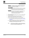
5. Grasp the latch and press the red release button, then rotate the latch
downward to disengage the module from the backplane connector. Carefully
slide the module out of the slot.
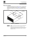
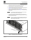
Figure 6-7. Removing a Power Supply Module
CAUTION! To avoid damaging the latch mechanism, press the red release
button all the way in before rotating the latch.
CAUTION!
To prevent overheating and possible damage to the switch, do not
operate the switch with an empty slot any longer than it takes to
install a new power supply module.
Release Button
Latch
Screw
Screw
Ground Jack