


4 – Installation
Installing a Switch
4-4 59043-06 A
0
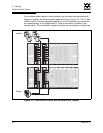
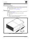
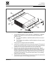
The switch is designed to be mounted in a rack using the mounting brackets and
the SANbox2-64 rail kit shown in Figure 4-2. To mount the switch in a rack, do the
following. Rack mounting instructions can also be found in the SANbox2-64 Rack
Mounting Guide packaged with the switch.
CAUTION!
I/O blade latches can be easily disengaged during
installation. Ensure that all of the I/O blade latches are up and
locked prior to applying power to the switch.
If the switch is mounted in a closed or multi-unit rack
assembly, make sure that the operating temperature inside the
rack enclosure does not exceed the maximum rated ambient
temperature. Refer to “Environmental” on page A-4.
The switch must rest on rails or a shelf in the rack or cabinet.
Allow 16 cm (6.5 in) minimum clearance at the front and rear of
the rack for service access and ventilation.
Do not restrict chassis air flow. Allow 16 cm (6.5 in) minimum
clearance at the front and rear of the rack for service access and
ventilation.
Multiple rack-mounted units connected to the AC supply
circuit may overload that circuit or overload the AC supply
wiring. Consider the power source capacity and the total power
usage of all switches on the circuit. Refer to “Electrical” on
page A-3.
Reliable grounding in the rack must be maintained from the
switch chassis to the AC power source.