


6 – Removal/Replacement
Cross-Connect Blades
59043-06 A 6-13
0
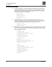
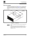
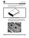
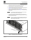
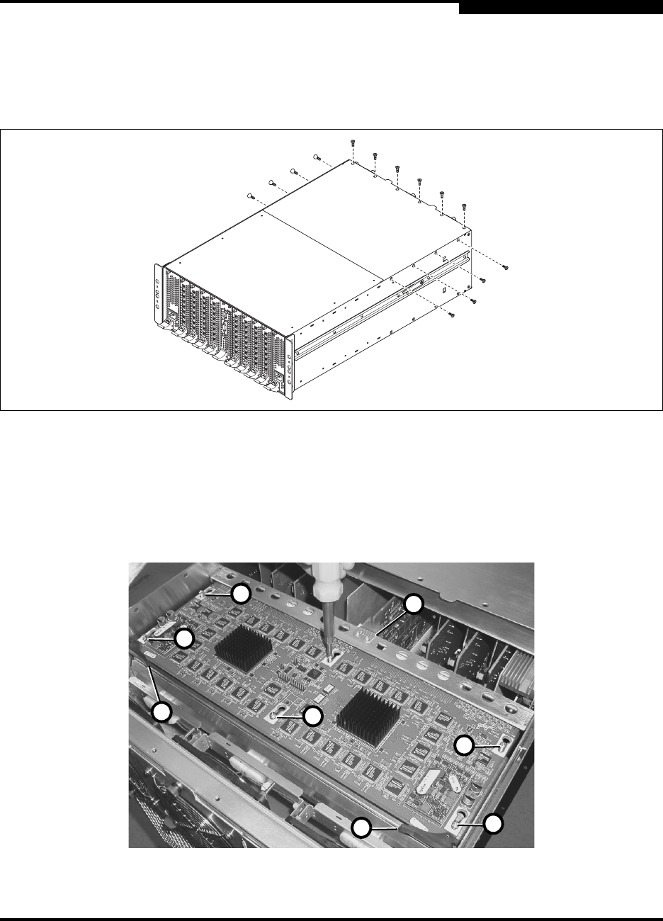
6. Remove the switch cover. Use a medium crosshead screw driver to remove
the four screws on each side and the six screws on top as shown in
Figure 6-4. Lift and remove the switch cover and set it aside. Put on an ESD
wrist strap and connect it to ground.
Figure 6-4. Switch Cover Removal
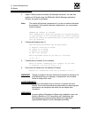
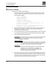
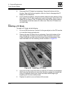
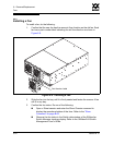
7. Remove the CC blade. Loosen the six screws (1) that fasten the CC blade to
the chassis as shown in Figure 6-5, but do not remove them. The three
screws nearest the latches (2) need only be loosened a couple turns. The
three screws nearest the backplane (3) must be backed off about 3/8 of inch
to allow enough clearance to remove the blade.
Figure 6-5. CC Blade Removal
3
1
1
1
1
2
2
1