


6 – Removal/Replacement
Cross-Connect Blades
6-14 59043-06 A
0
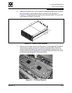
8. Disconnect the CC blade from backplane. Grasp both latches with the
thumbs. Open both latches together a little at a time to disengage the CC
blade from the backplane.
9. Lift CC blade from switch. Using the thumbs under the open latches, lift the
latch edge of the CC blade up enough to get a better grip. Gently lift the CC
blade from the switch. If the CC blade will not come off the screws nearest
the backplane, back the screws off a little more. Place the CC blade in an
anti-static bag.
6.4.2
Installing a CC Blade
To install a CC blade, do the following:
1. Put on an ESD wrist strap. Connect it to the ground jack on the CPU module
or to another chassis ground point.
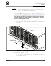
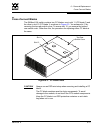
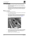
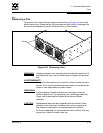
2. Remove the new CC blade from its packaging. Open both latches all the
way. Holding the CC blade by the latches, place the blade in the switch.
Center the blade key holes over the screws nearest the backplane, then
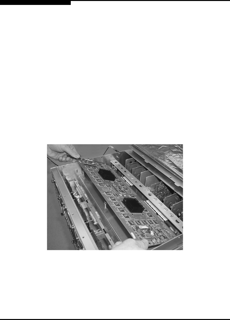
lower the blade over the remaining screws as shown in Figure 6-6.
Figure 6-6. Installing a CC Blade
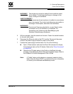
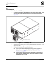
3. Using the thumbs, close both latches to seat the CC blade in the backplane.
When securing the latches, be sure that the latch engages the chassis tab.
Using a crosshead screw driver, fasten the blade screws finger tight
beginning with the two middle screws.
4. Replace the switch cover and fasten all the screws.