


2 – General Description
Chassis Controls and LEDs
2-4 59043-06 A
0
2.2
Chassis Controls and LEDs
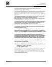
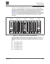
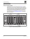
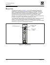
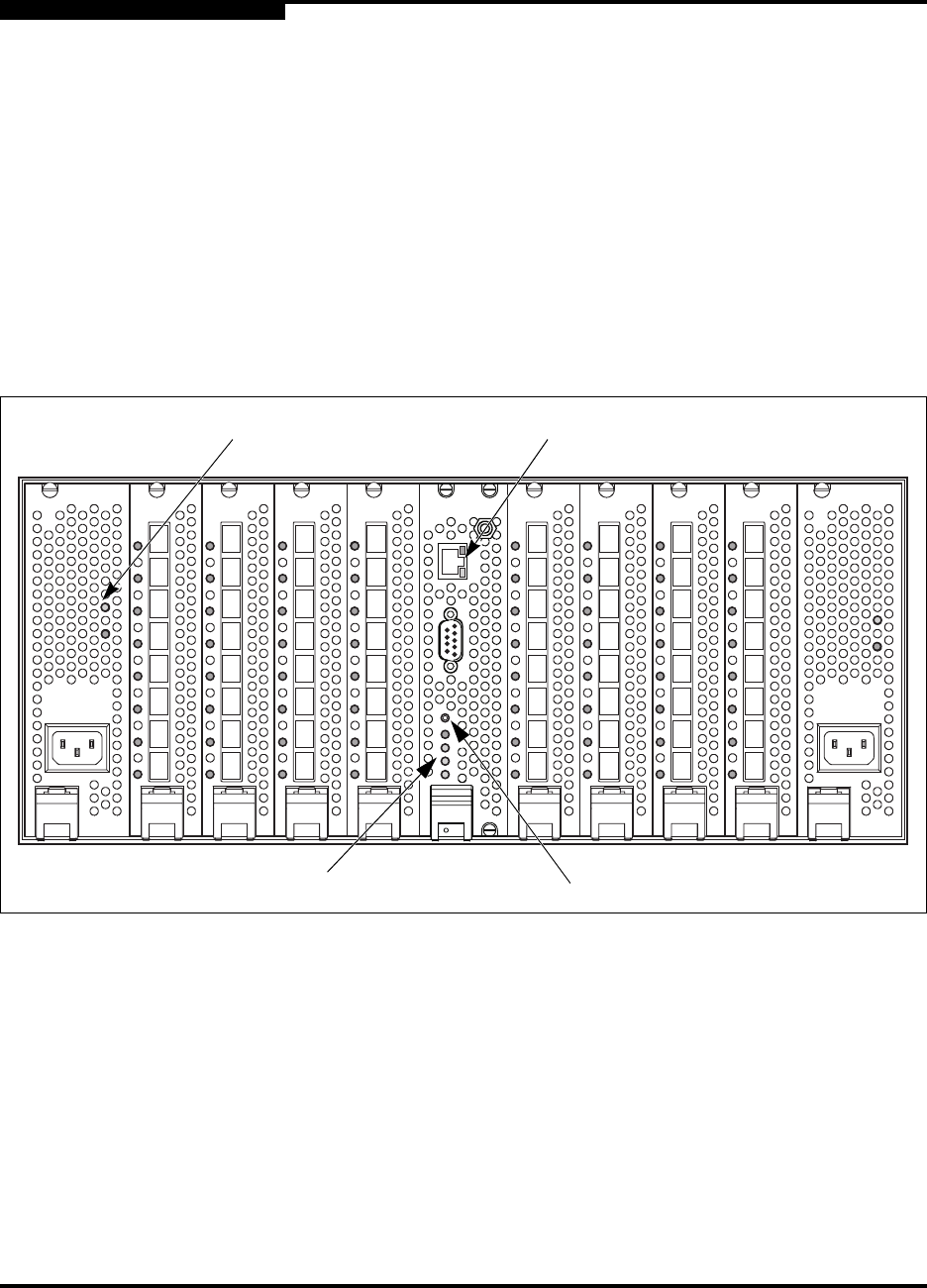
The Maintenance button on the CPU module, shown in Figure 2-3, is the only
chassis control and is used to recover a disabled switch. Power is applied to the
switch logic circuitry when one or both power supply modules are connected to a
110 or 230 VAC power source. The chassis LEDs are located on the CPU module
and provide information about the switch’s operational status. The chassis LEDs
provide information about the switch’s operational status. The chassis LEDs
include the Input Power LED, Heartbeat LED, Over Temperature LED, and the
Fan Fail LED. Refer to “Power Supply Modules” on page 2-12 for information
about power supply LEDs and to “Port Status LED” on page 2-8 for information
about the Port Status LED.
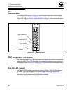
Figure 2-3. Chassis Controls and LEDS
Maintenance
Button
Chassis LEDs
Power
Supply LEDs
Ethernet
Port LEDs